Disassembly#
Summary#
The Librem 16 is deliberately made easy to repair and upgrade. By removing a few screws, you can easily replace or upgrade the battery, Wi-Fi module, RAM, and M.2 SSDs.
You can find replacement parts in the Purism shop, or use our CAD models to customize your own. Standard part specifications are also available.
Materials#
You will need:
A Phillips #0 screwdriver
A tool to open the small connectors, such as a plastic opening tool or your fingernail
An organizer or container to store the removed screws
If you are removing the wireless card, you will need a tool to release the coaxial cables, such as a plastic opening tool or a small flathead screwdriver.
Procedure#
Before you begin#
Ensure that the Librem 16 is completely powered off.
Disconnect all cables from the Librem 16.
Remove the D-shell#
Carefully remove the D-shell (bottom panel) screws, and store them in a container for safekeeping.
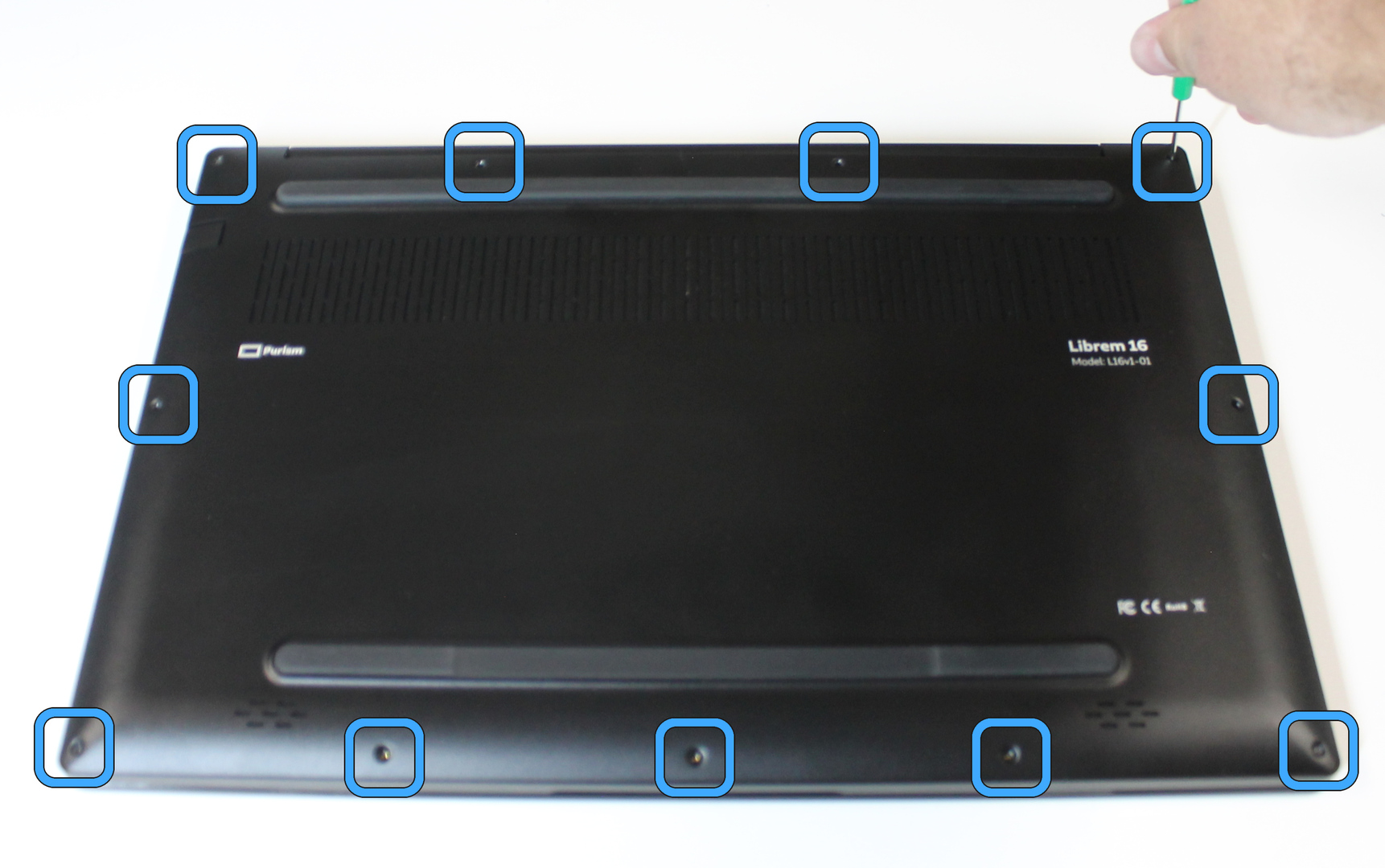
Lift the D-shell to remove it.
Disconnect battery#
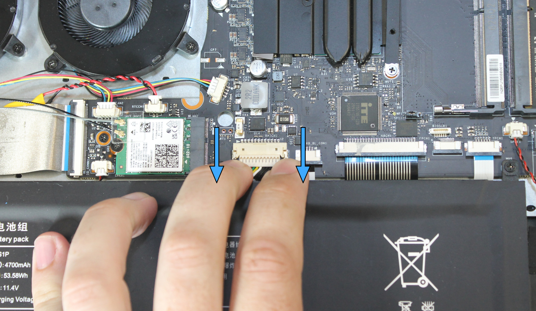
Disconnect the battery by sliding the battery plug out of the socket. Do not pull the wires. Pull both sides of the plug, so the plug slides straight out.
Important
Don’t skip this, even if you don’t plan on removing the battery. Dropping a screw on the mainboard near the battery connector can cause a short if the battery is connected.
Remove memory and storage modules#
Release the memory modules (DIMMs) by bending the retention levers away from each DIMM until they release.
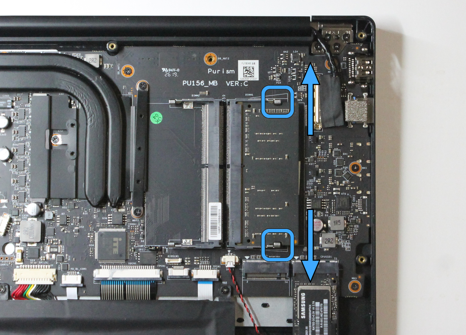
Remove the memory modules by sliding them straight out of each socket.
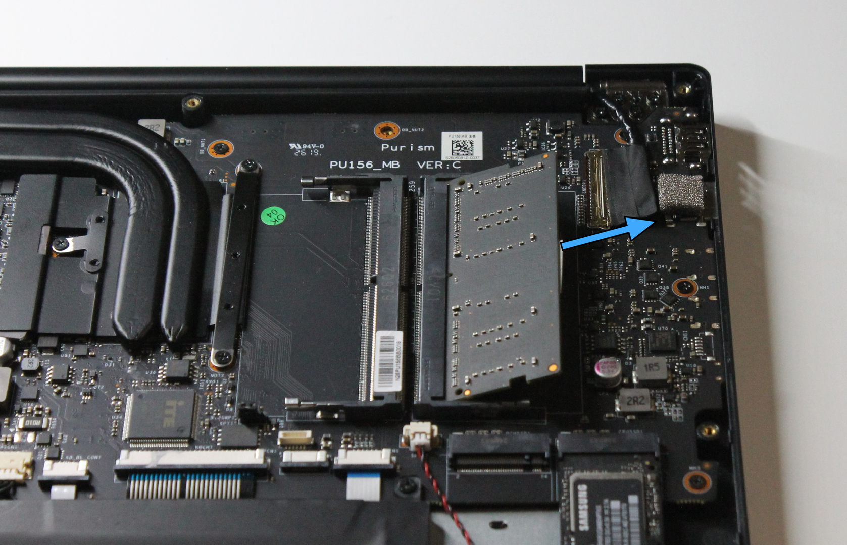
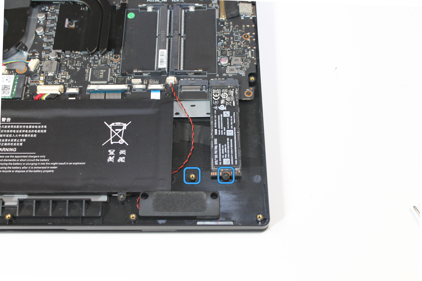
Release the storage modules (SSDs) by removing each screw.
Remove the storage modules by sliding them straight out of each socket.
Remove battery#
Remove 6 screws securing the battery.
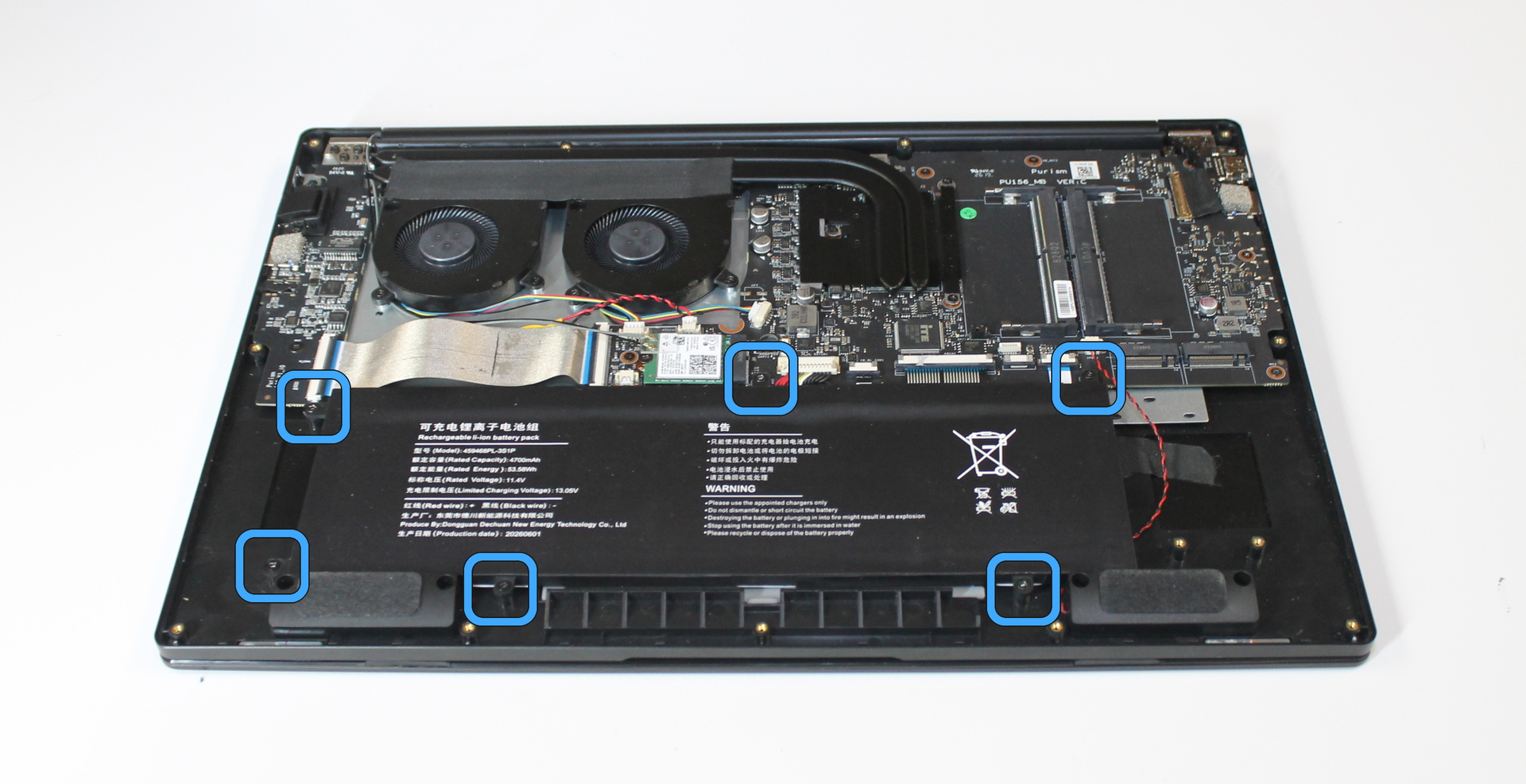
Lift the battery out of the chassis.
Remove I/O cable#
These flat cable connectors are secured by a black lever integrated into the connector. Release each lever securing the I/O cable in each connector. Slide a fingernail or plastic opening tool under the center of the lever, and gently pull up.
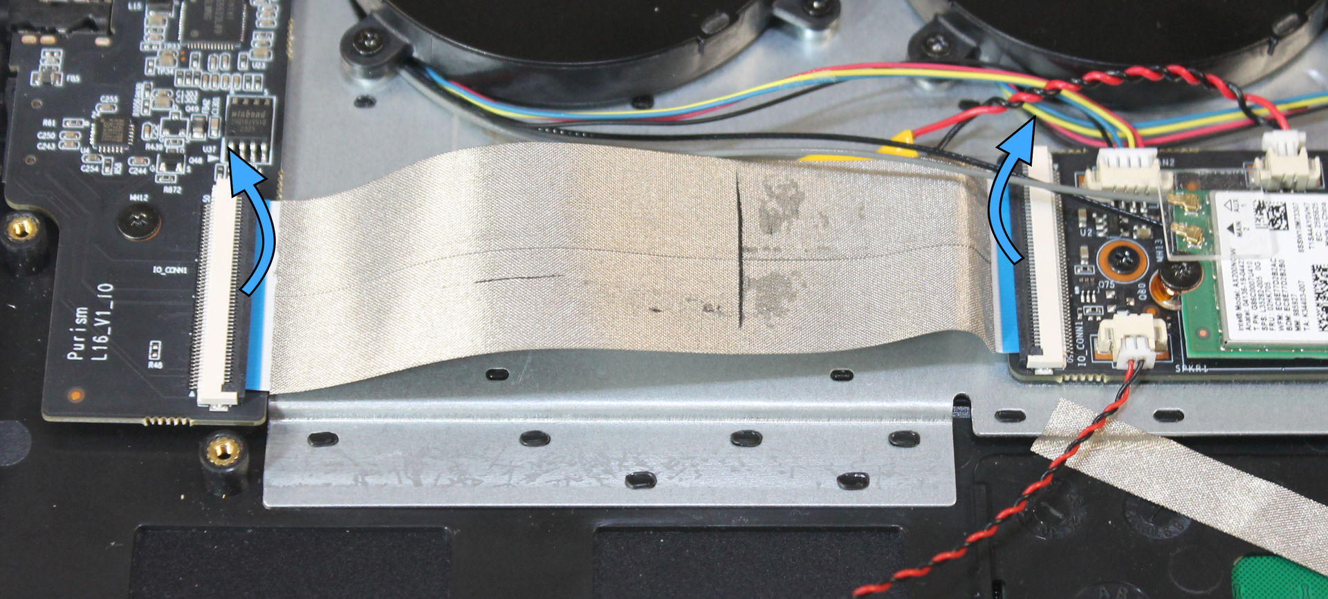
If the cable is taped down, gently remove the tape and discard it. Lift the I/O cable out.
Remove touchpad cable#
If either touchpad cable connector is covered by tape, gently remove the tape.
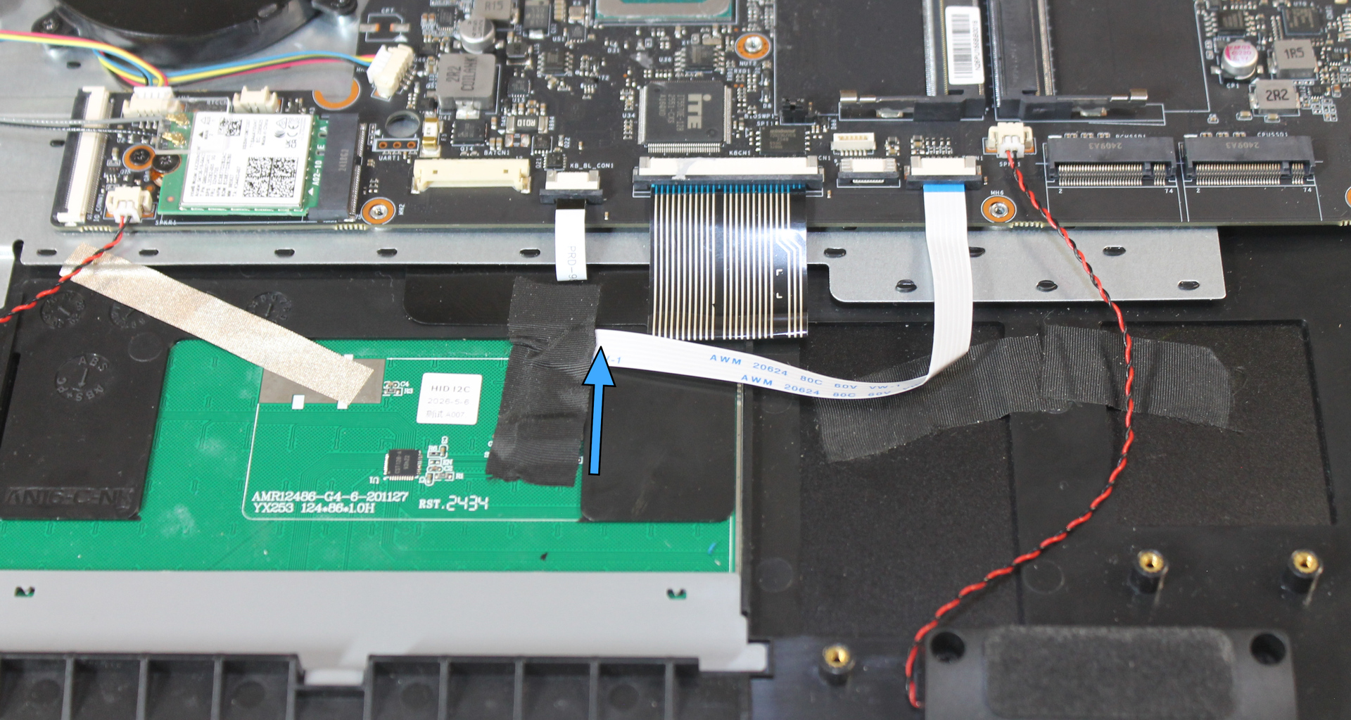
Release the black lever on the touchpad side connector by inserting a fingernail or plastic opening tool under the center of the lever, then gently pulling up.
Release the mainboard side connector by sliding the black slide downward from each end.
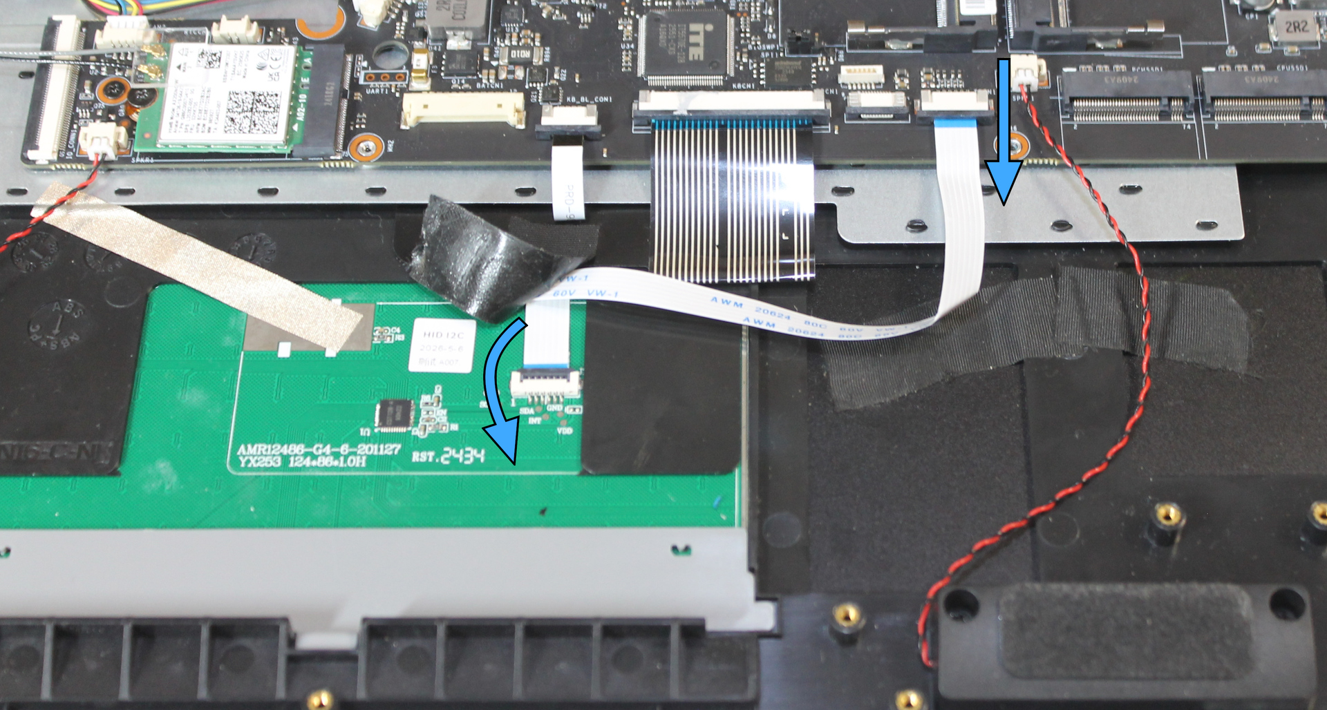
Lift the touchpad cable out.
Remove heatsink#
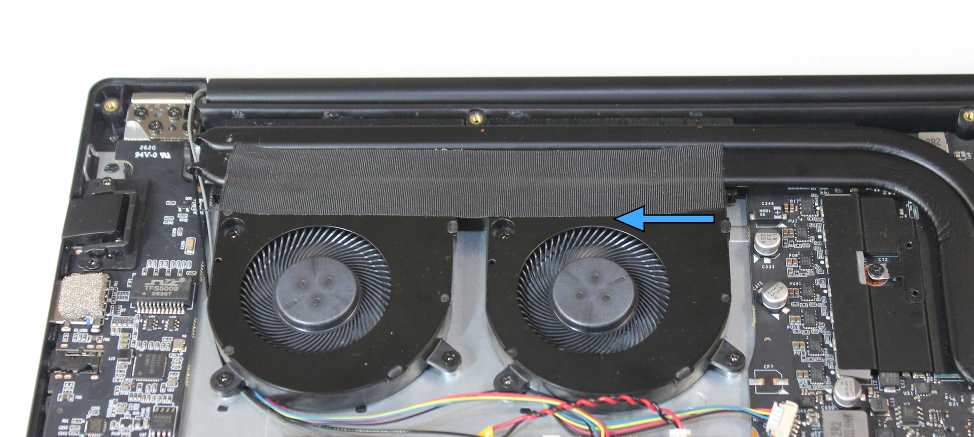
Gently remove the tape sealing the fans to the heatsink. As long as the tape is in good condition, it can be reused during reassembly. Keep it in a safe place.
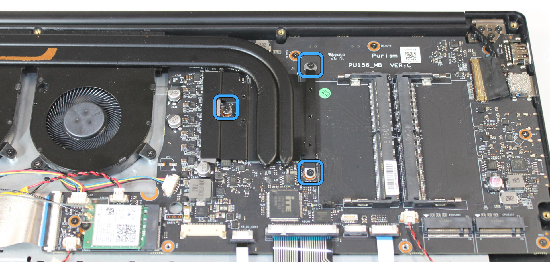
Remove three screws securing the heatsink. Loosen each screw slightly first, then remove all screws, to avoid placing uneven force on the CPU. Keep it in a safe place.
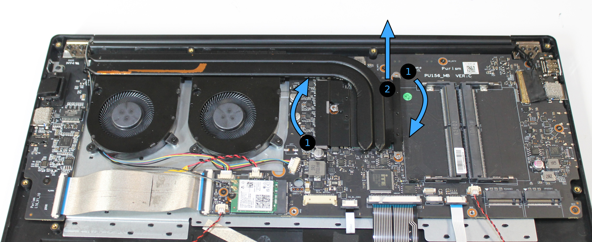
Lift the heatsink off of the CPU. If the thermal compound resists lifting, twist the heatsink slightly to break the seal. Do not apply excessive lifting force to avoid damaging the CPU connections to the mainboard. Avoid touching the thermal compound on either side; it cannot be reused if it is contaminated with fingerprints or dirt.
Disconnect cables#
Lift the retention lever on the display connector with a fingernail or plastic opening tool.
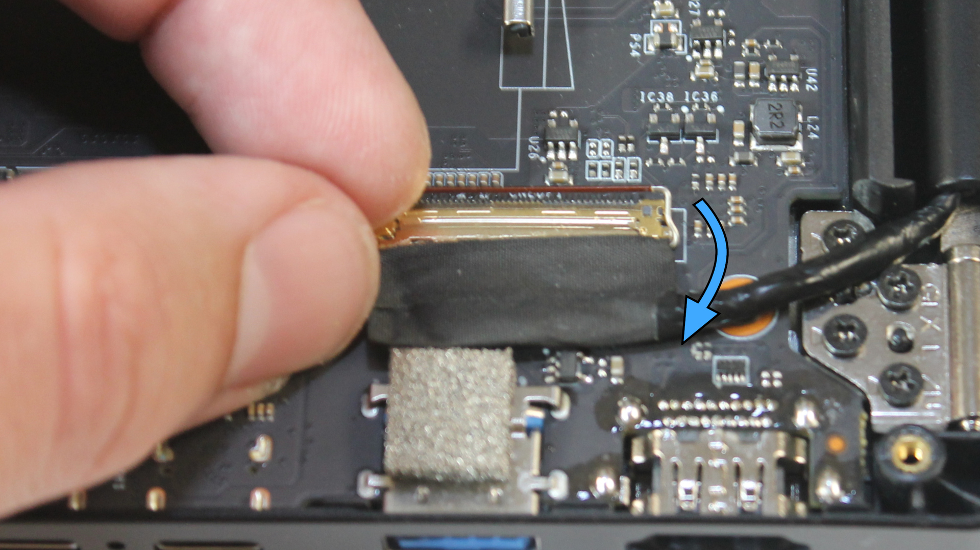
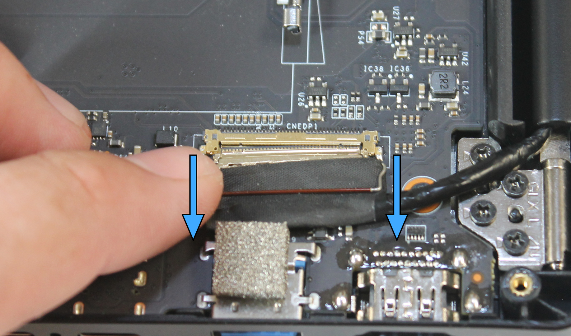
Slide the display connector out of the socket by pulling from both ends. Do not pull on the wires or sheathing.
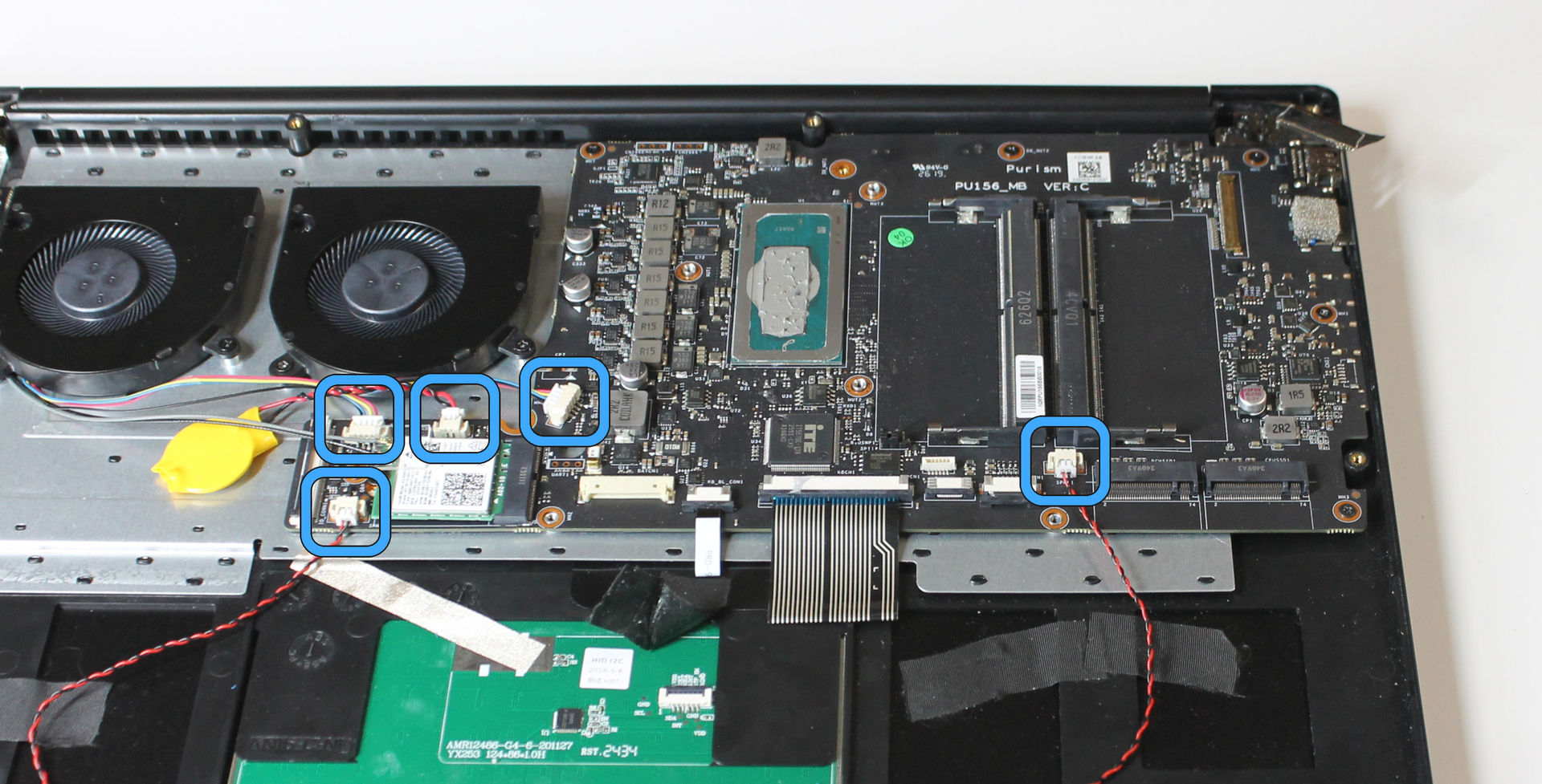
Disconnect the wafer connectors for each fan, each speaker, and the coin cell battery. Pull the connector from the socket from each end. Do not pull on the wires.
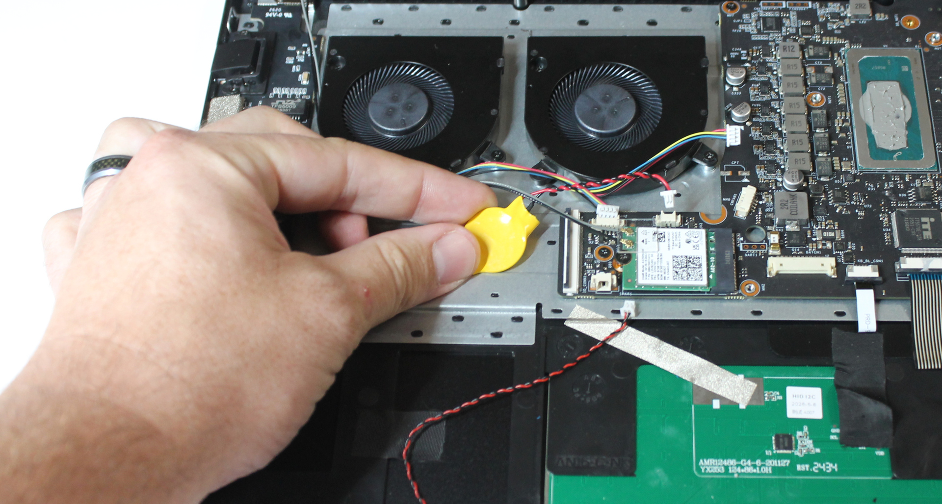
Remove the coin cell battery by peeling it from the chassis. Peel the coin cell itself by gripping the insulator. Do not pull on the wires.
Disconnect the flat connectors for the keyboard and keyboard backlight. Slide the black retention slide downward from each end, then lift the cable out.
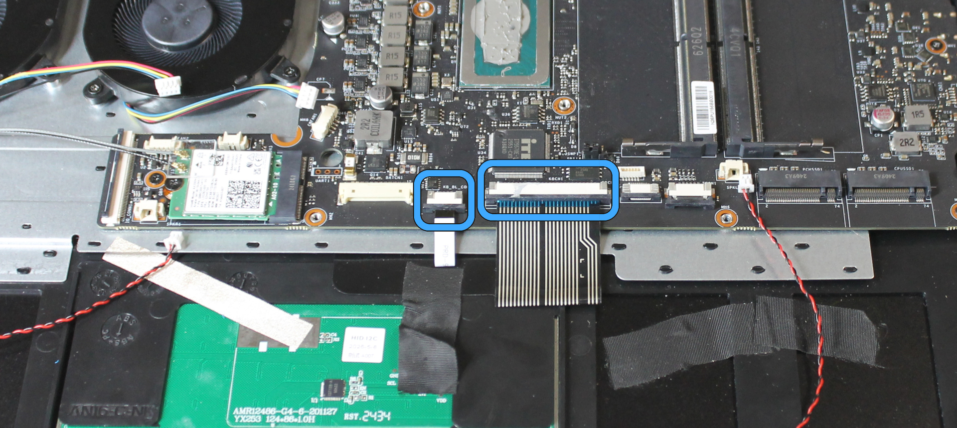
Remove wireless card#
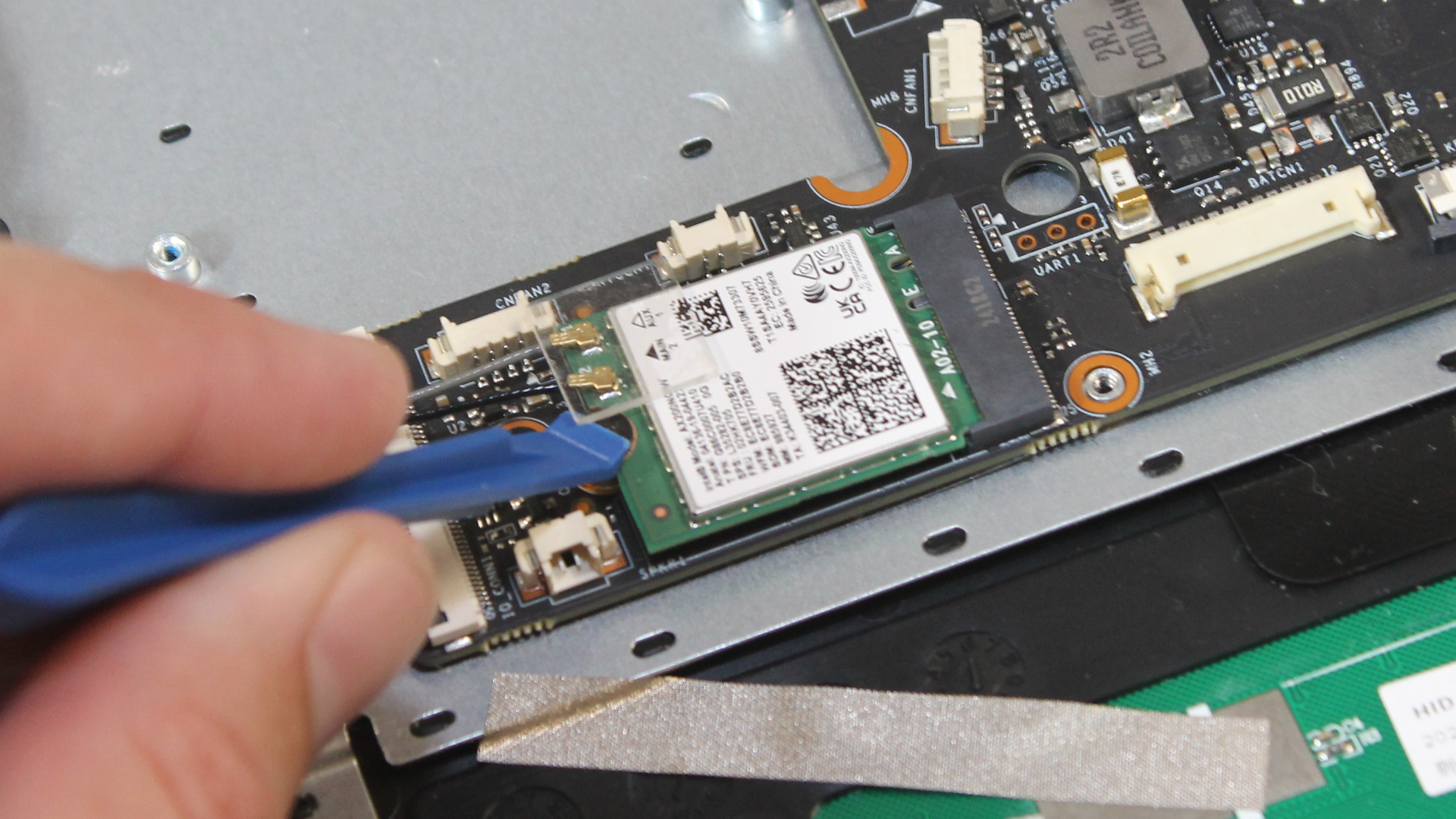
Remove the coaxial cable retainer (plastic square) by prying it off of the wireless card. Keep it in a safe place, so the adhesive is not contaminated with dirt.
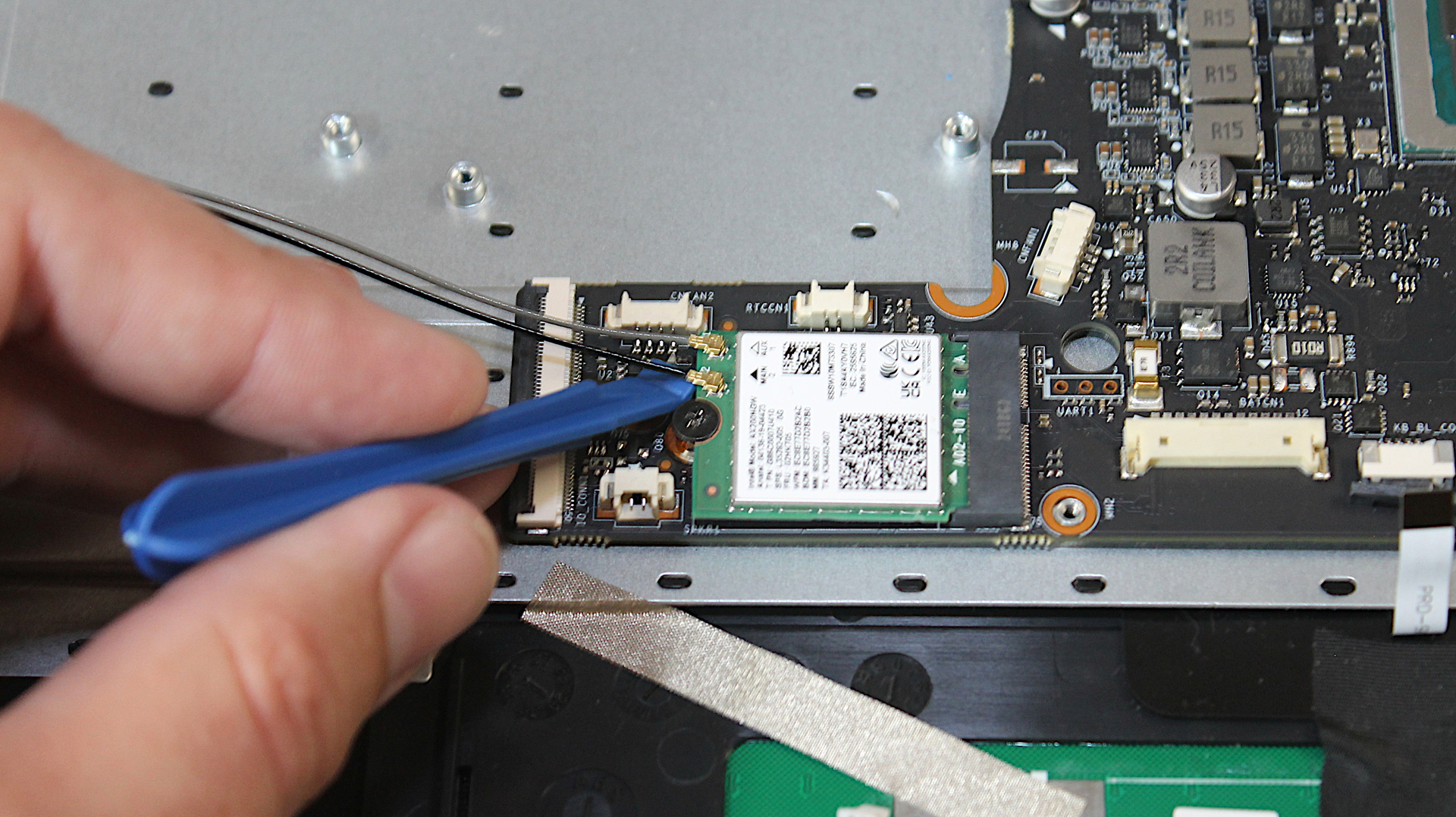
Remove each coaxial cable. Slide a plastic opening tool or fine flat screwdriver under the connector, near the socket, then pull the cable upward.
Important
Do not use tweezers, as they may prevent the connector from releasing the socket. Do not pull the wires.
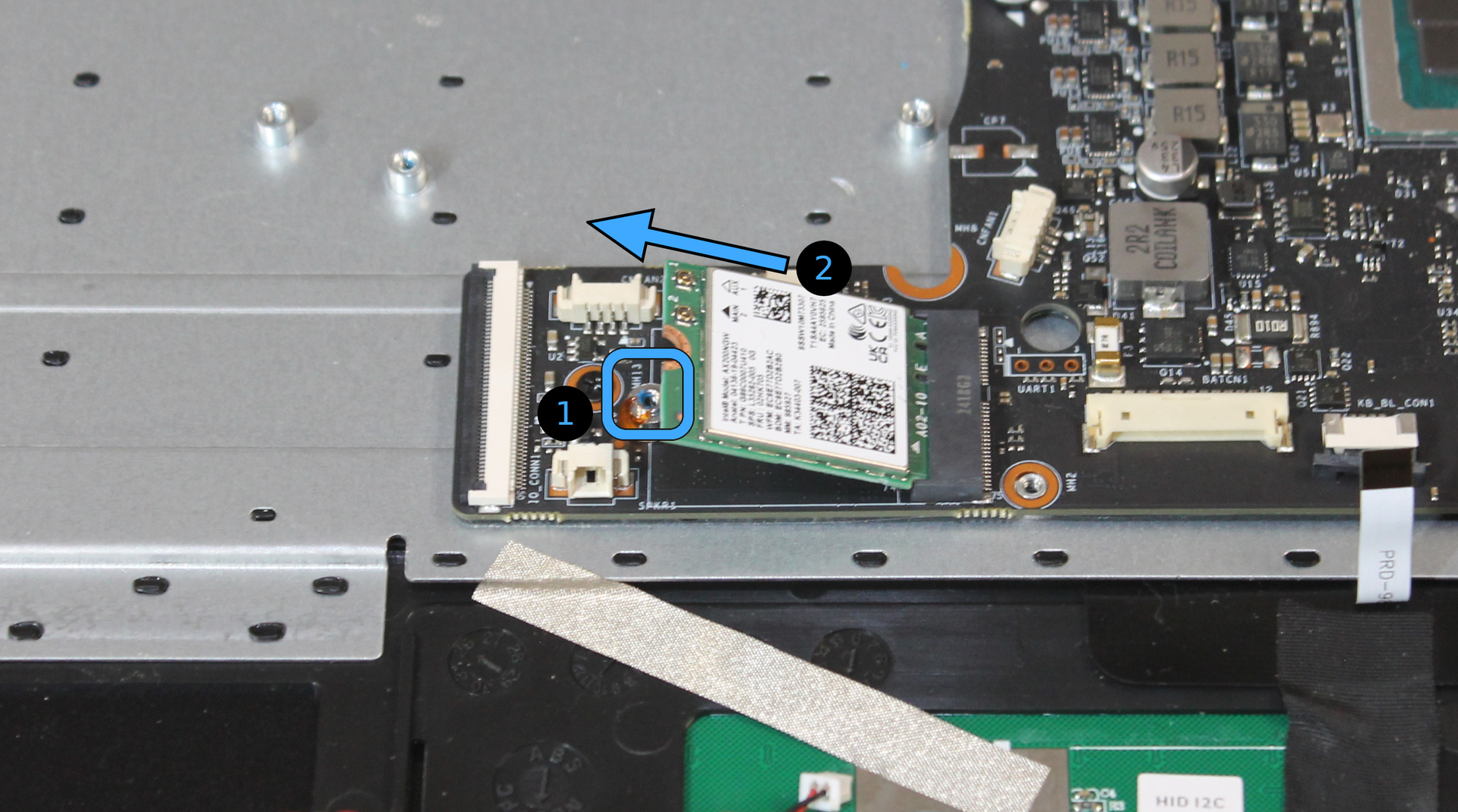
Remove the screw securing the Wi-Fi card, and pull the card straight out of the socket.
Remove fans#
Remove three screws securing each fan.
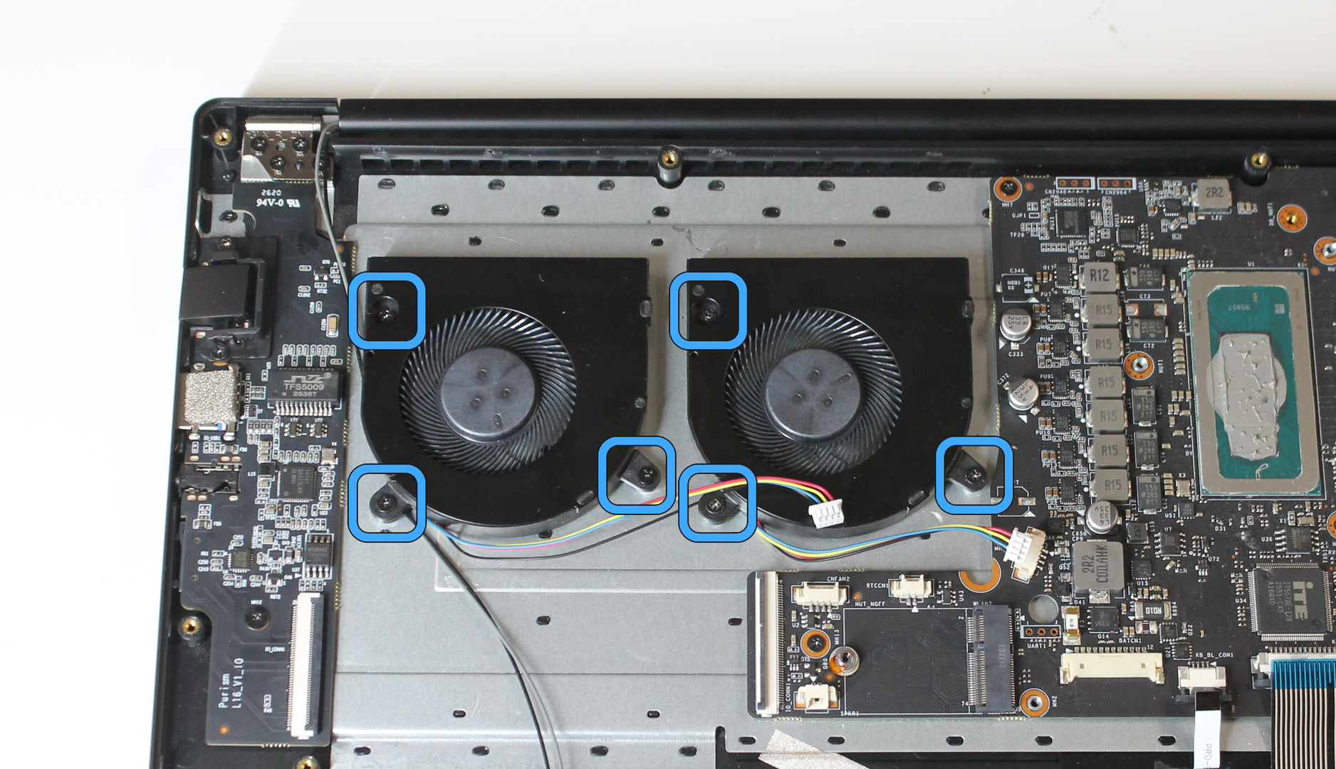
Lift the fans out of the chassis.
Remove display assembly#
Fully open the Librem 16 display, and support it so the hinge is not under tension.
Remove 4 screws from each hinge.
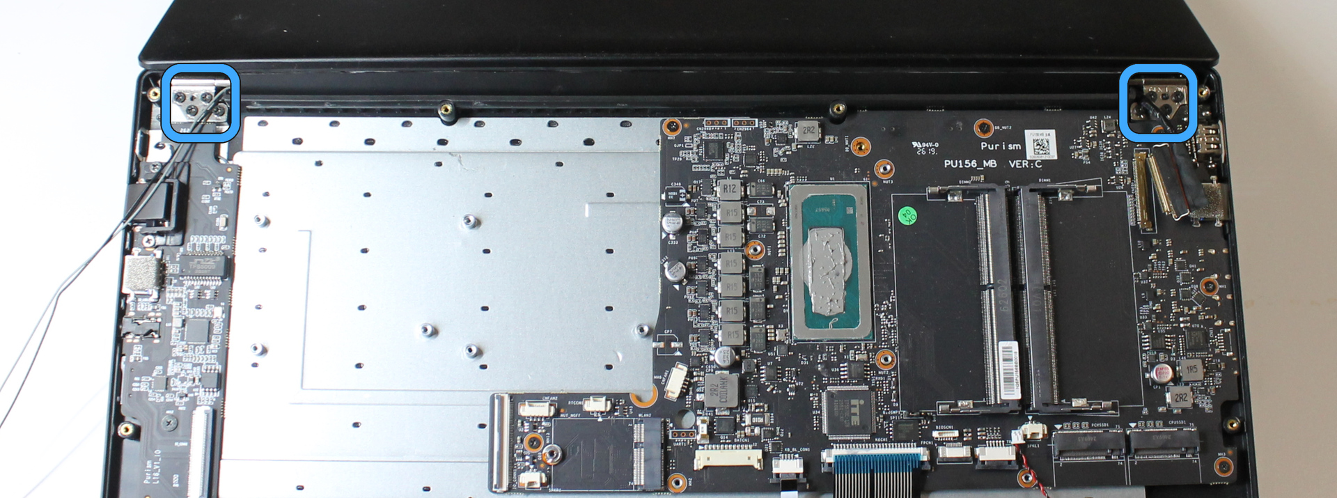
Lift the bottom chassis away from the hinges to separate the display assembly.
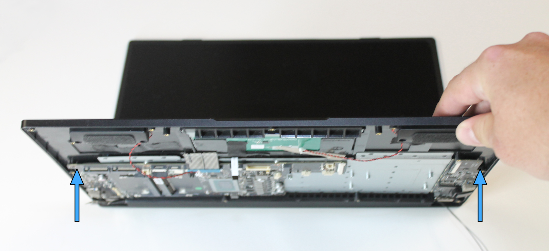
Remove mainboard#
Remove 7 screws securing the mainboard.
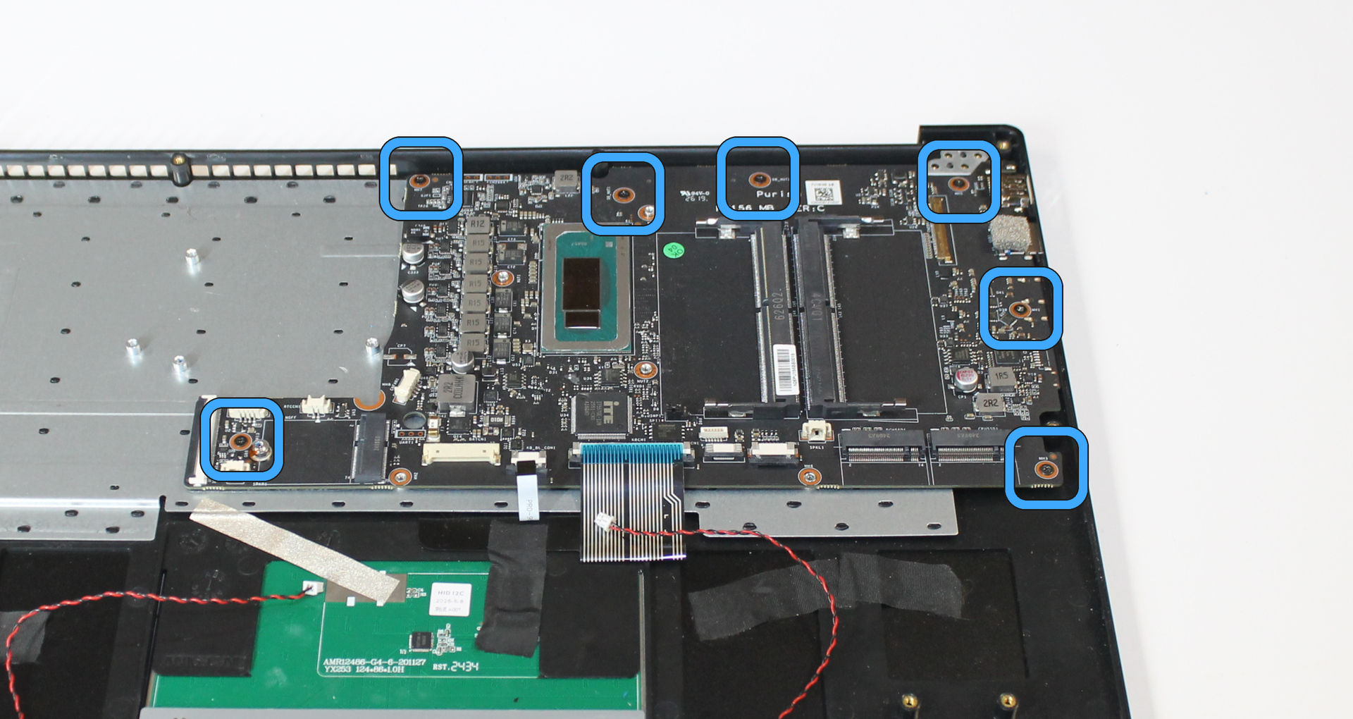
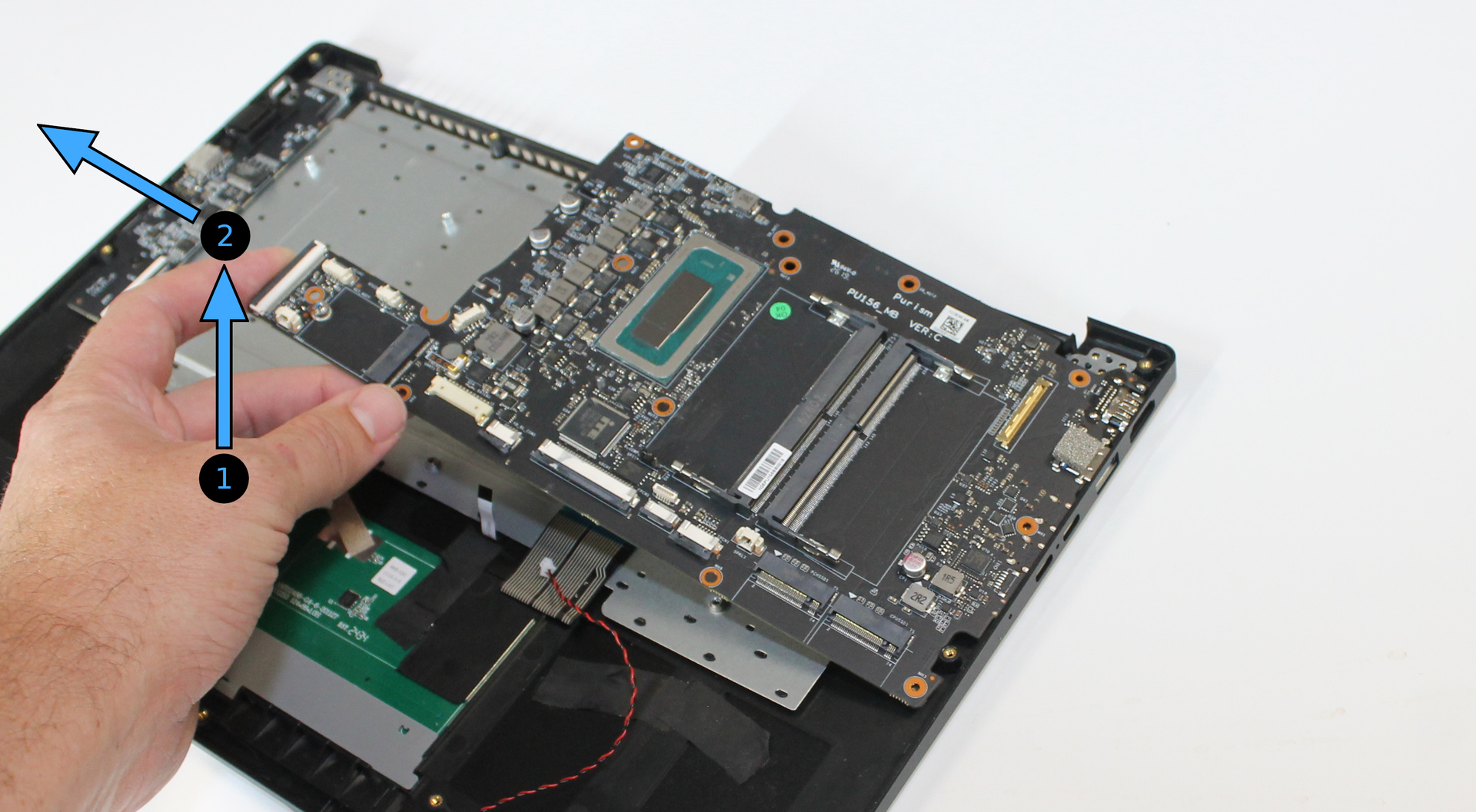
Lift the edge of the mainboard near the fans.
Slide the mainboard out of the chassis edge to remove it.
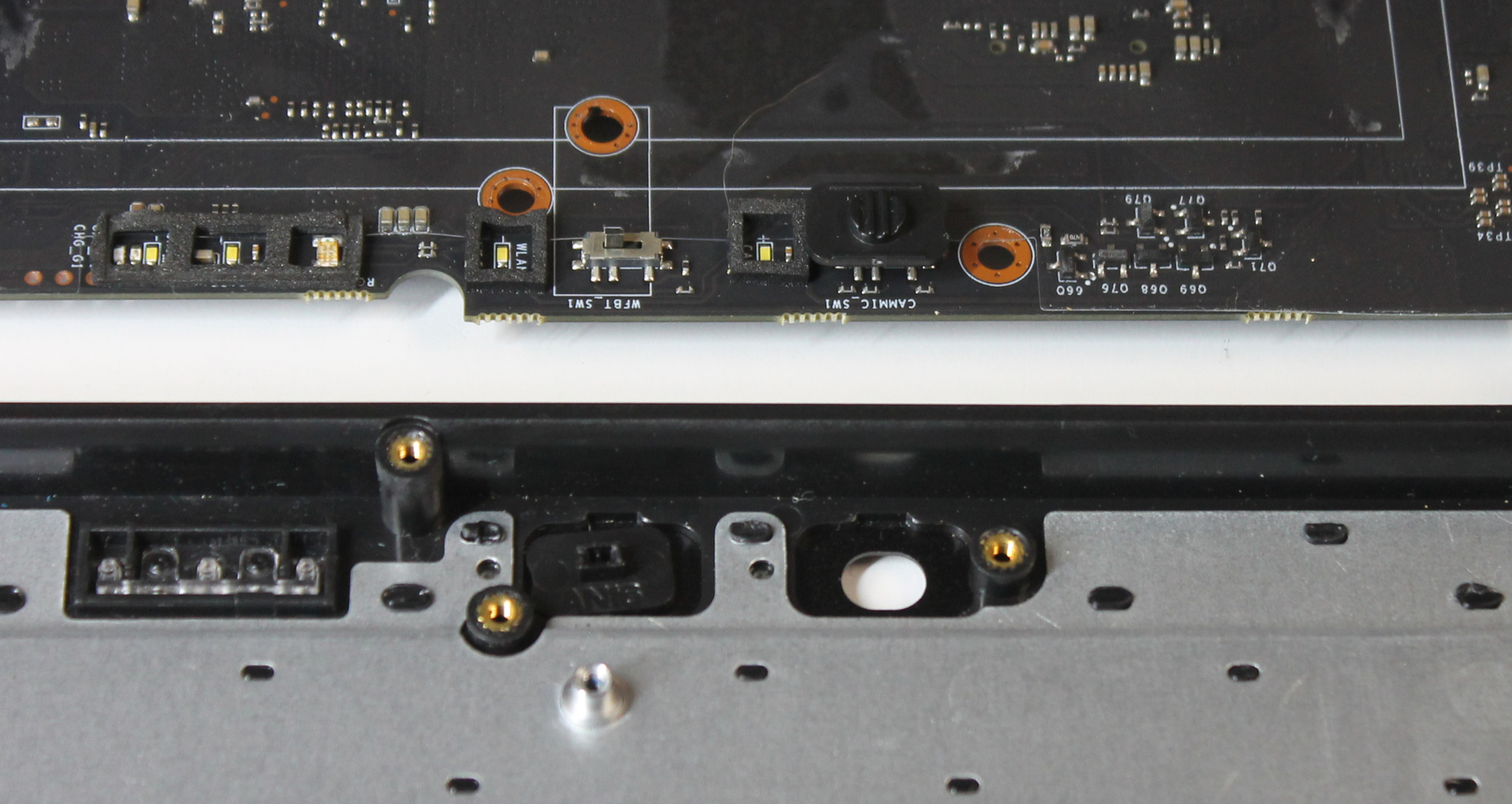
Locate the kill switch caps, which may be retained by the mainboard or remaining in the chassis, and remove them.
Remove I/O board#
Remove 2 screws securing the Ethernet cover. Hold down the Ethernet cover while removing the screws, so it does not spring away from the board.
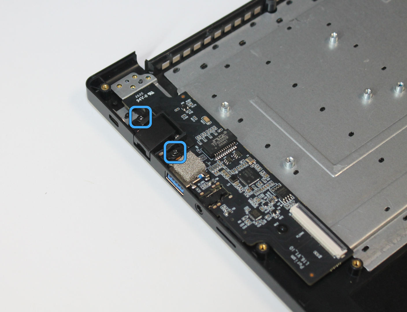
Remove the Ethernet cover.
Remove 1 screw securing the I/O board.
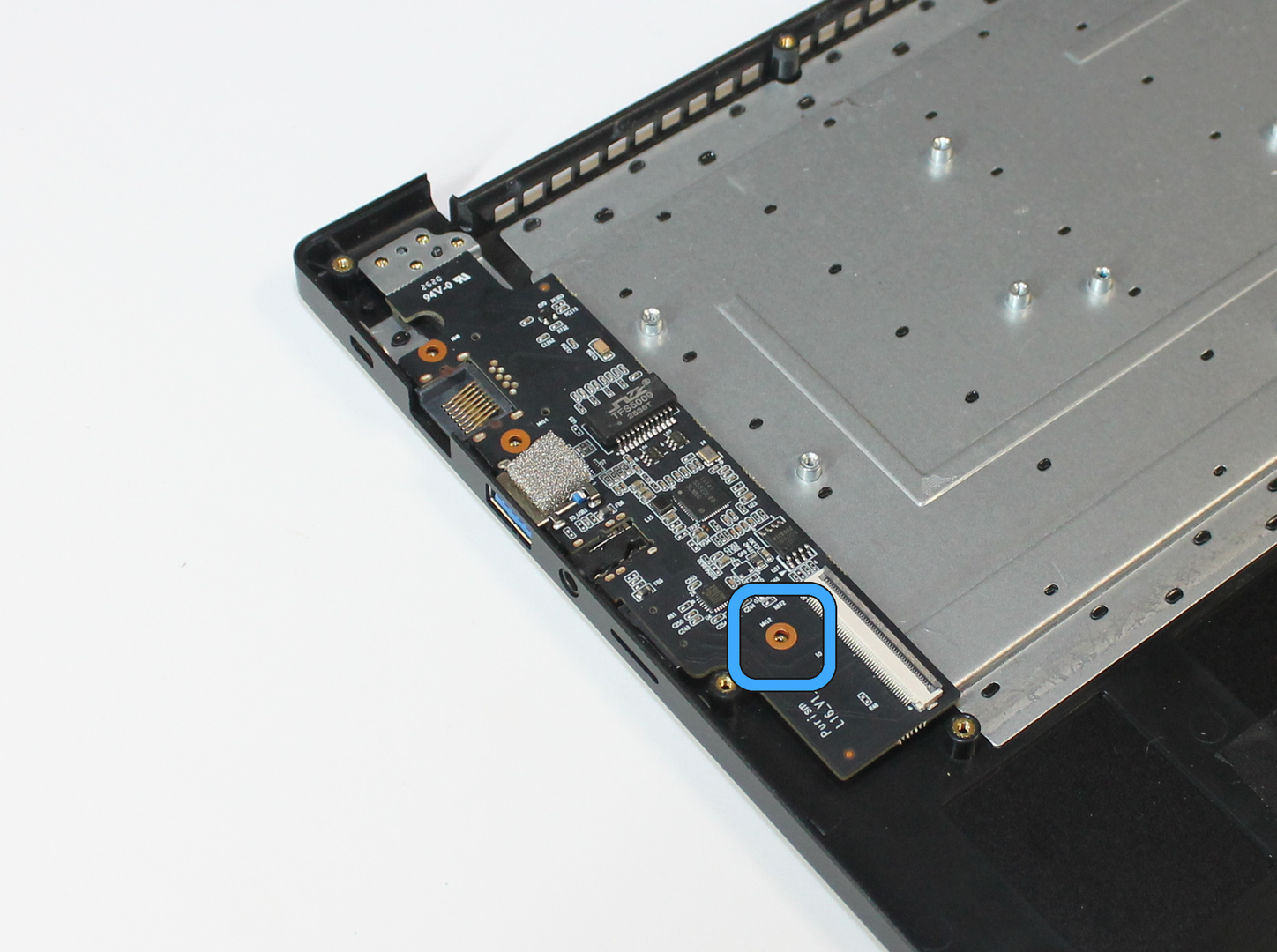
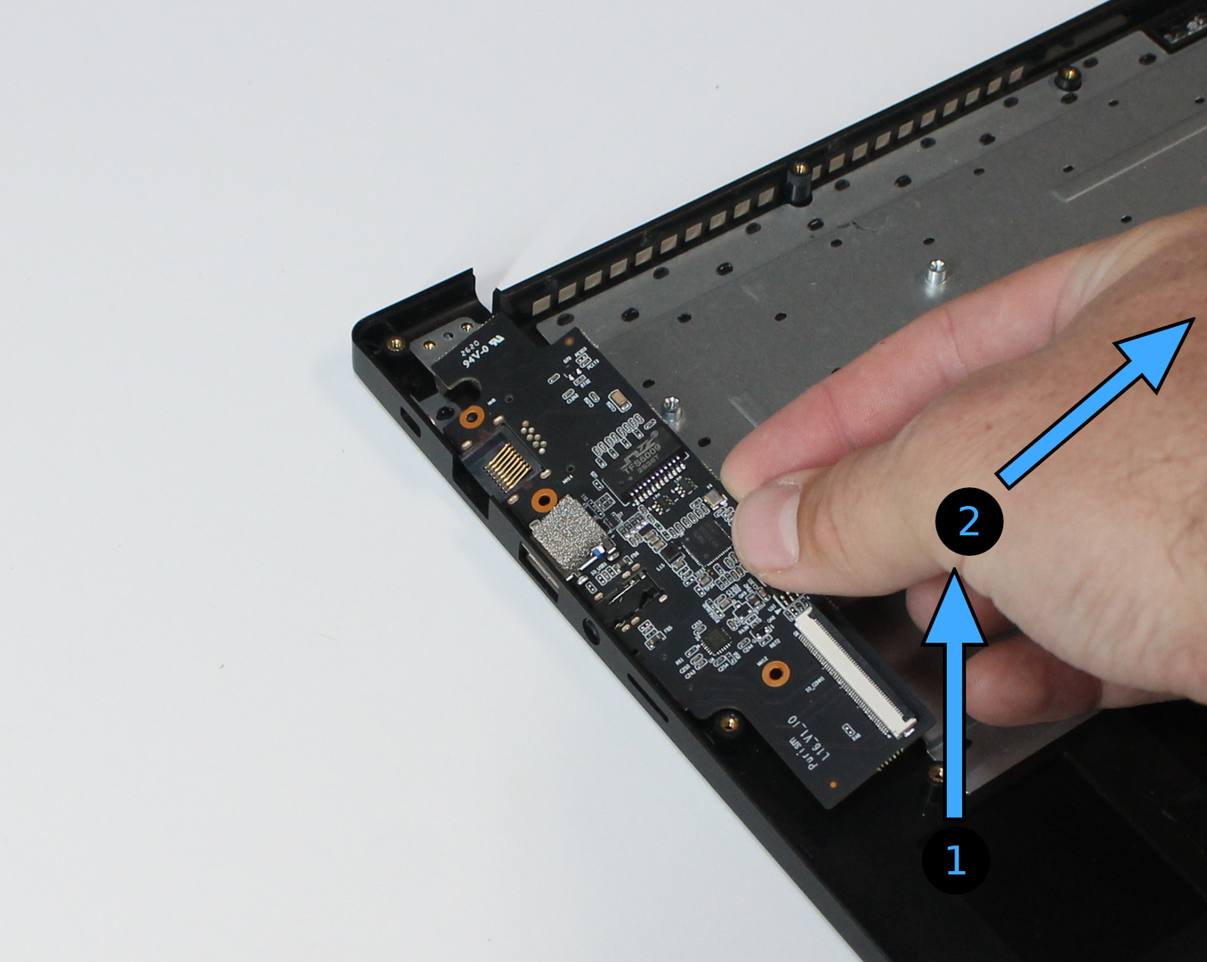
Lift the edge of the I/O board near the fans.
Slide the I/O board out of the chassis edge to remove it.
Remove speakers#
Remove 2 screws securing each speaker.
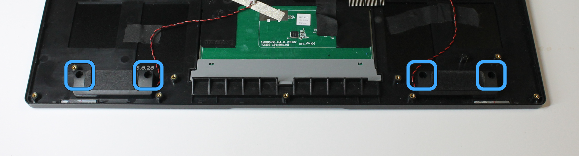
Lift each speaker out of the chassis.
Re-assembly#
To re-assemble the Librem 16, follow the assembly procedure.