Chassis#
Overview#
The Librem 5 is designed for longevity with lifetime software updates. Longevity also implies being able to repair a device outside of warranty. Purism plans to stock replacement components in the shop in case you need to replace your modem, camera, or even the main PCB.
Warning
Disassembling your Librem 5 may risk damaging it. Any damage from disassembly is not covered in the warranty. Contact Purism Support if your Librem 5 is under warranty before attempting this process.
See also
Downloadthe video
These steps outline the process of fully disassembling the Librem 5 or Liberty hone.
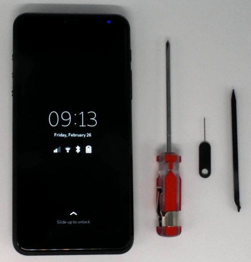
Materials#
1x #0 Phillips-head screwdriver
1x SIM tray removal tool
1x plastic pick or spudger
Disassembly#
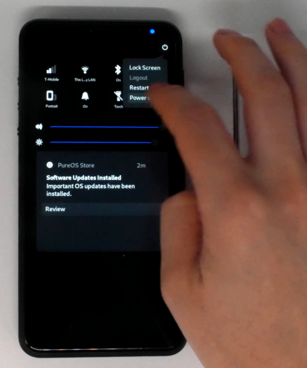
Completely power down the device.
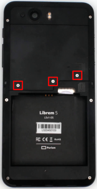
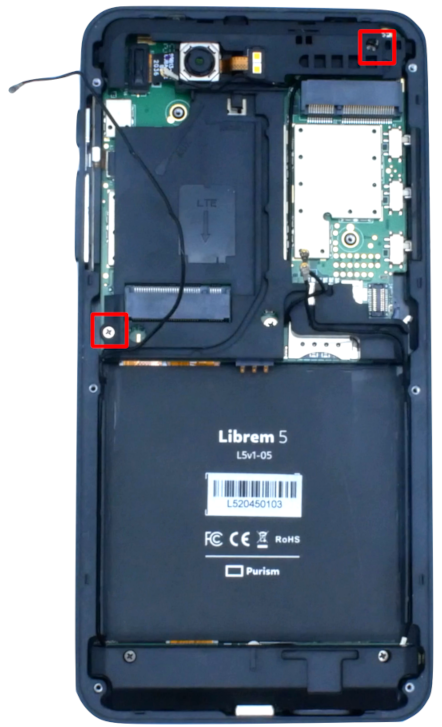
Remove 3 screws holding the modem cover.
Note
These screws are shorter than the rest of the screws, so keep them separate.
If you have a smart card installed, remove it now.
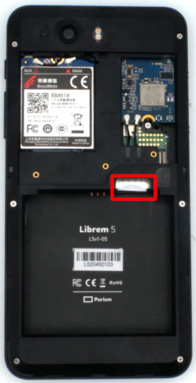
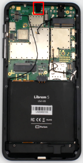
Remove the WiFi/Bluetooth module.
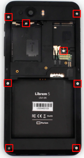
Remove 8 screws retaining the internal frame.
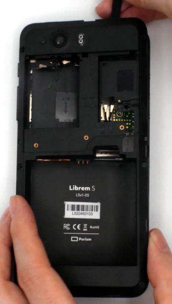
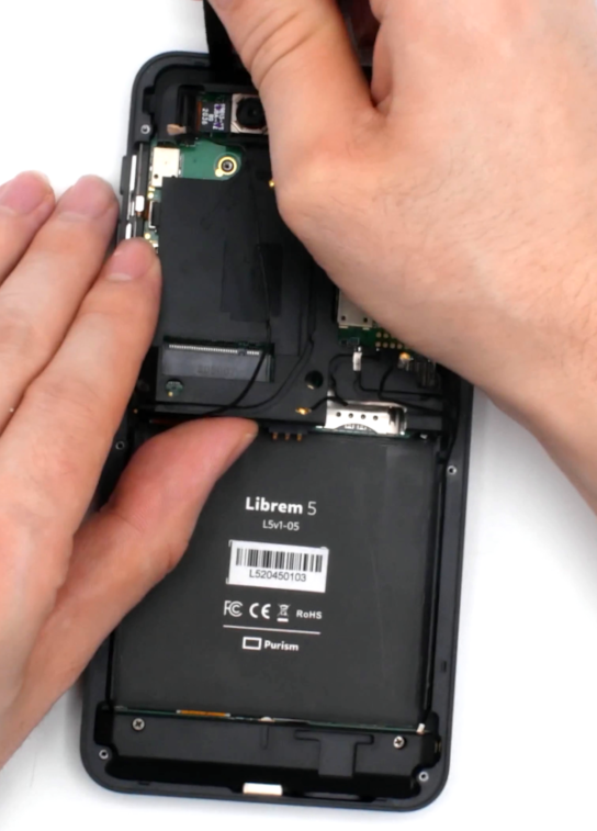
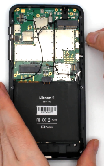
Use a plastic pick or spudger to release several friction clips around the outside border of the frame.
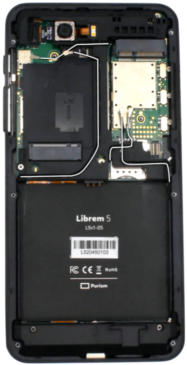
Carefully pull the antenna cables from the plastic frame.
Caution
Pulling too hard on an antenna cable will dislodge it from the PCB.
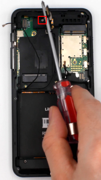
Remove the 2 screws retaining the center frame.
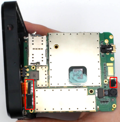
Unplug the main camera and remove the screw hidden by FPC.
The center frame can now be removed. Use a plastic pick or spudger to remove 2 friction clips at the top left and right of the frame.
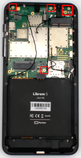
Remove PCB screws.
Caution
Be careful about screw lengths and keep the case screws and PCB screws separate. Using a long case screw in a PCB screw hole can damage the screen.
The 3 screws at the top connect the antennas, so do not forget to reinstall them during reassembly.
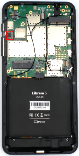
Carefully remove the microphone cover and store it in a safe place. It is easily lost.
Gently pull the hardware kill switch alignment tab up and out of the frame.
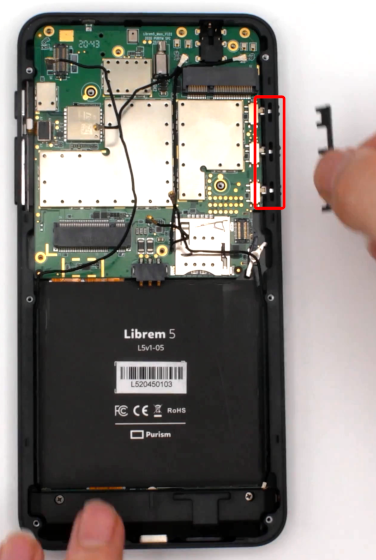
Remove the 3 hardware kill switches.
Unplug the Power/Volume FPC.
Lift the PCB out until you can see the Display and USB-C FPC cables.
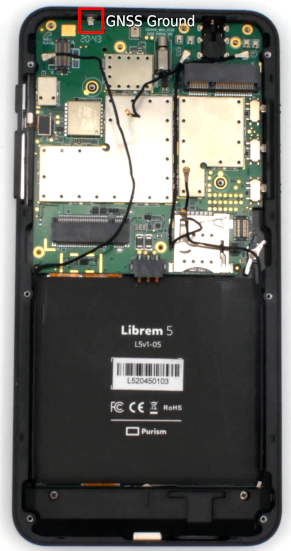
Caution
When removing the PCB be careful of the spring clip against the frame. This spring clip is part of the GNSS antenna assembly. GPS reception will become practically nonexistent if this spring clip breaks off.
Caution
There is a cover over the proximity sensor that is easy to lose. Put it in a safe place. If the device is reassembled without this cover, the proximity sensor will trigger automatically, and would need to be disabled.
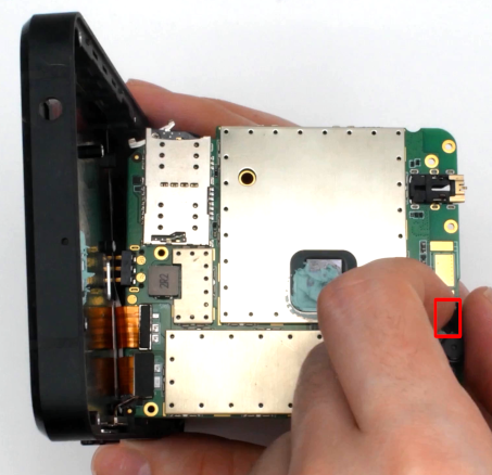
Carefully disconnect the USB C and Display FPC cables.
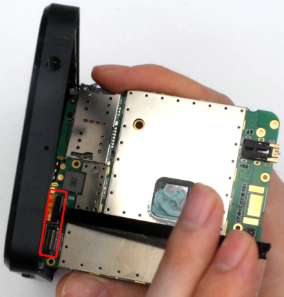
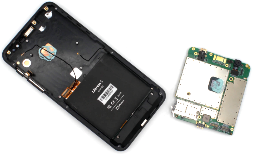
The remainder of the PCB can be removed after unplugging the final two FPC cables.
Reassembly#
Follow this procedure in reverse order to reassemble the device. If the thermal paste looks satisfactory, begin by reattaching the PCB to the FPC cables and reattaching the proximity sensor cover.