Assembly#
Summary#
After disassembling your Librem 16, you can reassemble it using this procedure.
The Librem 16 uses four types of screws. To identify each type, refer to the part specifications.
Materials#
You will need:
A Phillips #0 screwdriver
A tool to close the small connectors, such as a plastic opening tool (spudger) or your fingernail
If you need to replace the thermal compound, you will need:
Replacement high quality thermal compound
Lint free cloth
Cleaning solvent, 100% acetone or 91% isopropyl alcohol
If you need to replace the tape sealing the fans, you will need replacement linen or Kapton tape.
Procedure#
Install speakers#
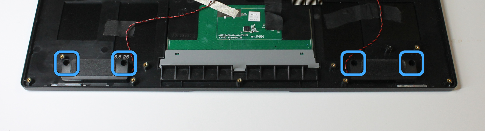
Place the speakers in the chassis. The speakers are different - the cables exit the speaker on different sides. Orient the speakers so the cables are near the touchpad.
Secure each speaker with 2 chassis screws.
Install I/O board#
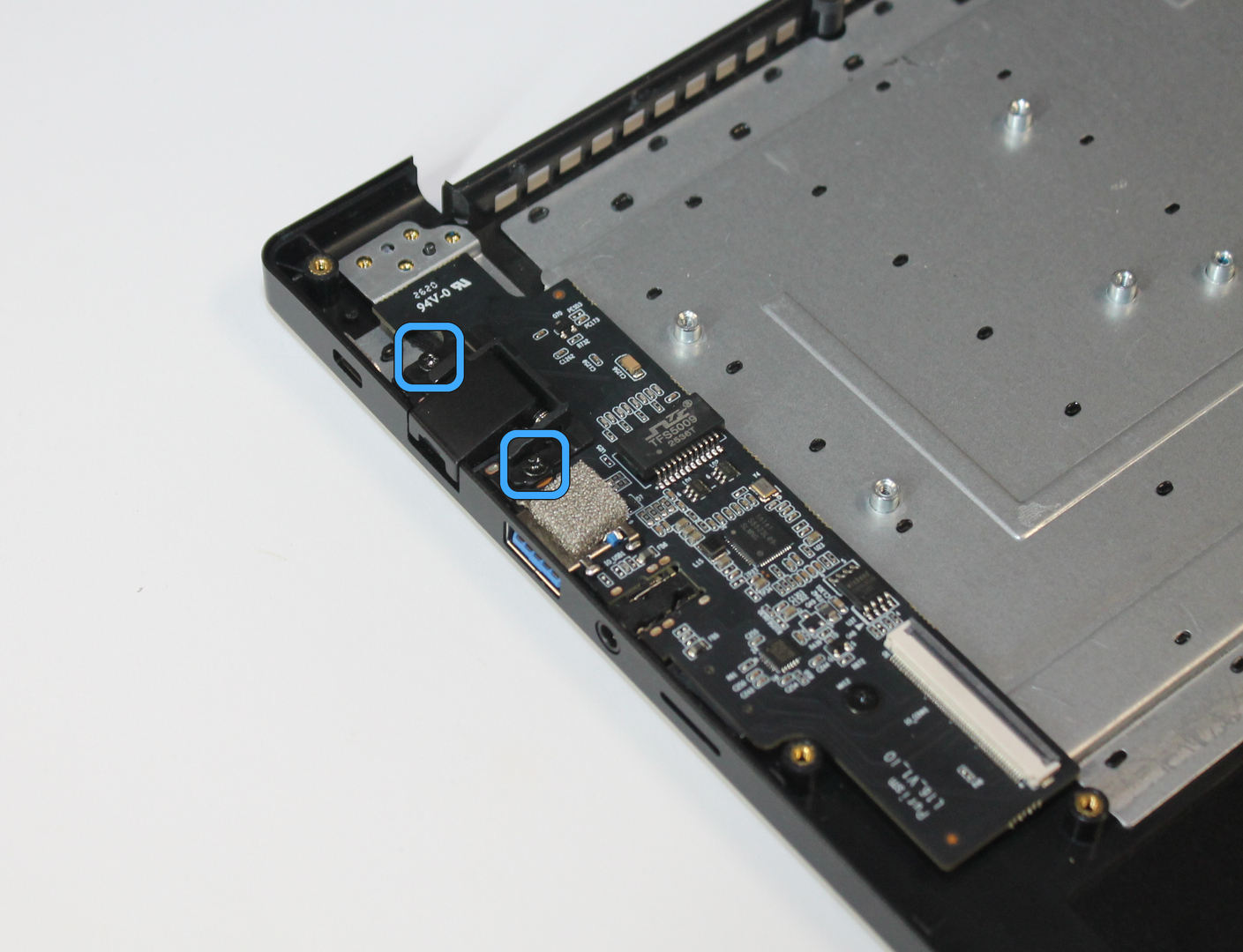
Insert the I/O board into the chassis edge, and ensure that the ports fit into the chassis cutouts.
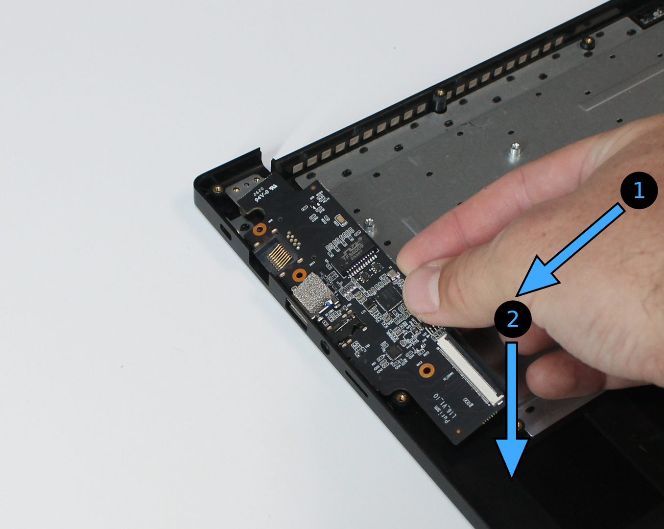
Lower the I/O board onto the screw holes, and check for alignment.
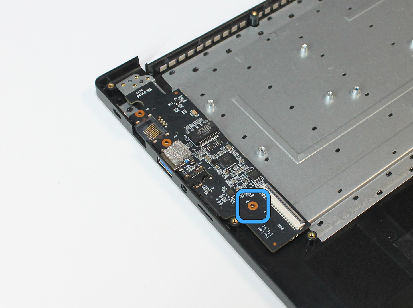
Secure the I/O board with 1 card screw.
Hold the Ethernet cover over the Ethernet jack, aligning the screw holes.
Secure the Ethernet cover with 2 chassis screws.
Install kill switch caps#
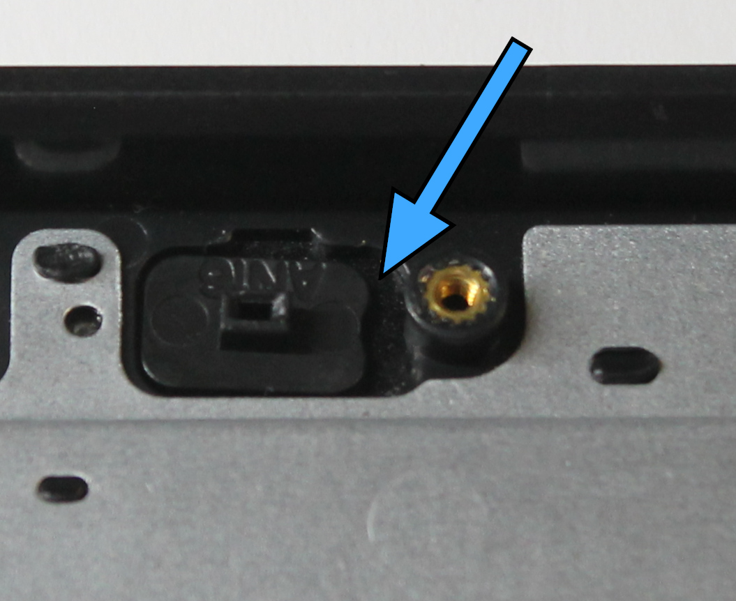
Place the kill switch caps into the holes in the chassis. Orient the notches toward the screw post.
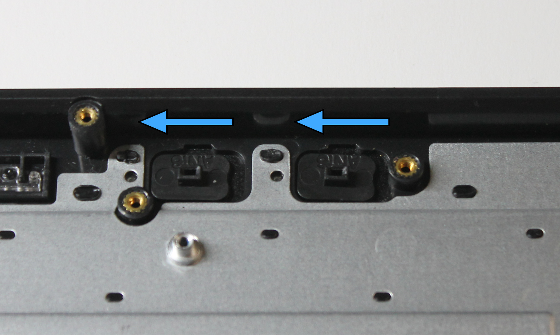
Slide them toward the I/O board.
Install mainboard#
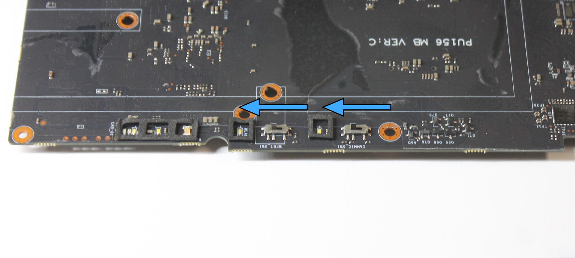
Slide the mainboard kill switches toward the fan side, away from the USB ports, so they will align with the kill switch caps.
Insert the mainboard into the chassis edge, and ensure that the ports fit into the chassis cutouts.
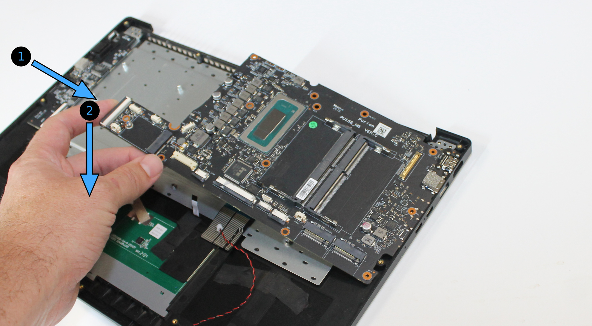
Lower the mainboard onto the screw holes, and check for alignment.
Ensure that no cables are trapped below the mainboard; move them if so.
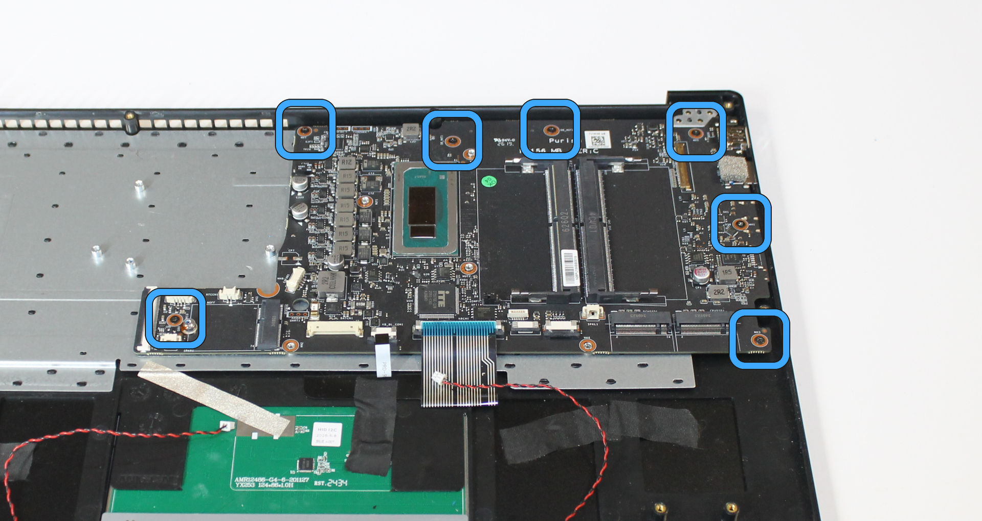
Secure the mainboard with 7 mainboard screws. Do not install screws in the two mainboard holes for the battery or in the three holes for the heatsink.
Install display assembly#
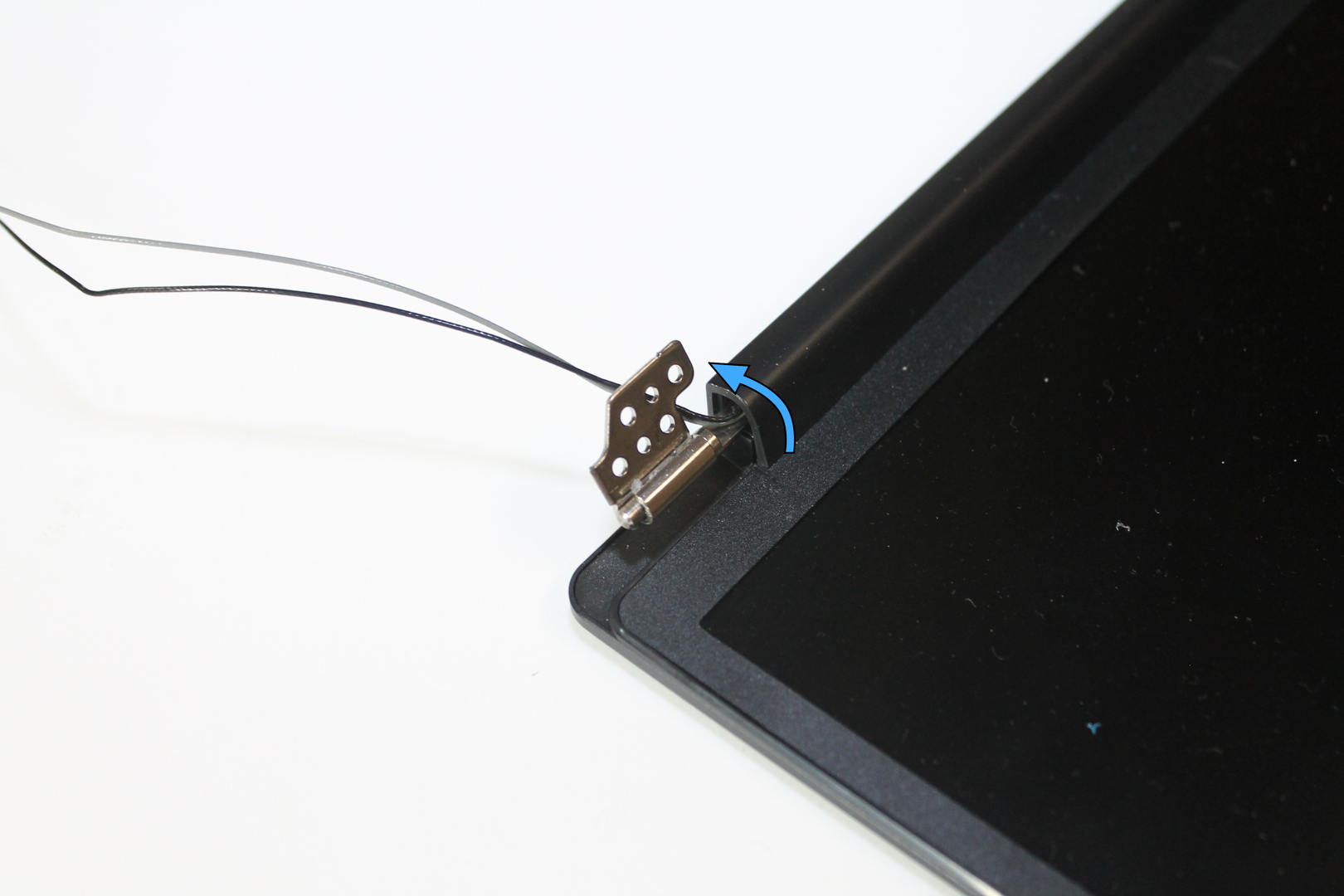
Ensure the display assembly hinges are in the open position. If they are not, lift them manually.
Place the chassis onto the mainboard hinges, and ensure the guide posts fit into the hinge holes.
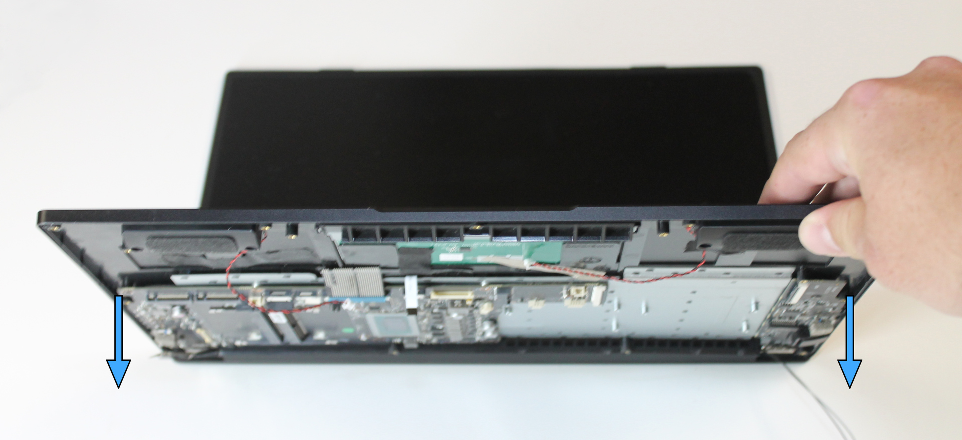
Install 4 chassis screws into each hinge.
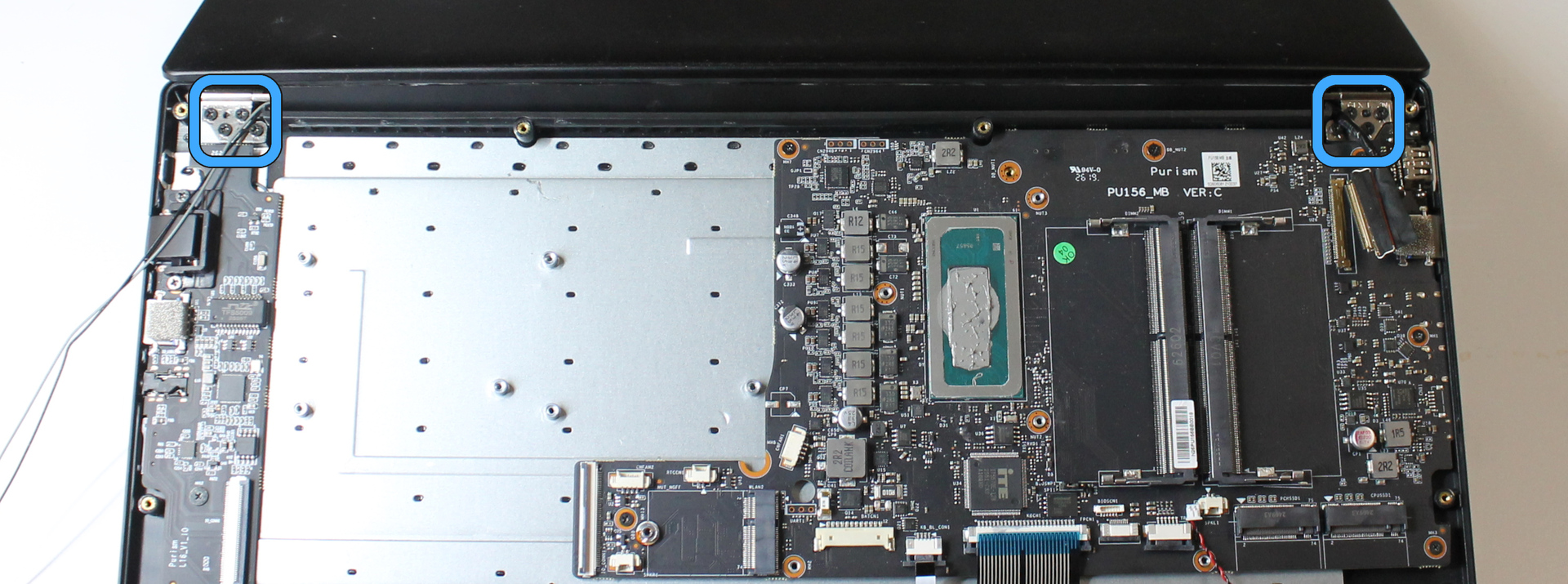
Close the Librem 16 display.
Install wireless card#
Insert the wireless card into the M.2 socket near the fans.
Secure the card with one card screw.
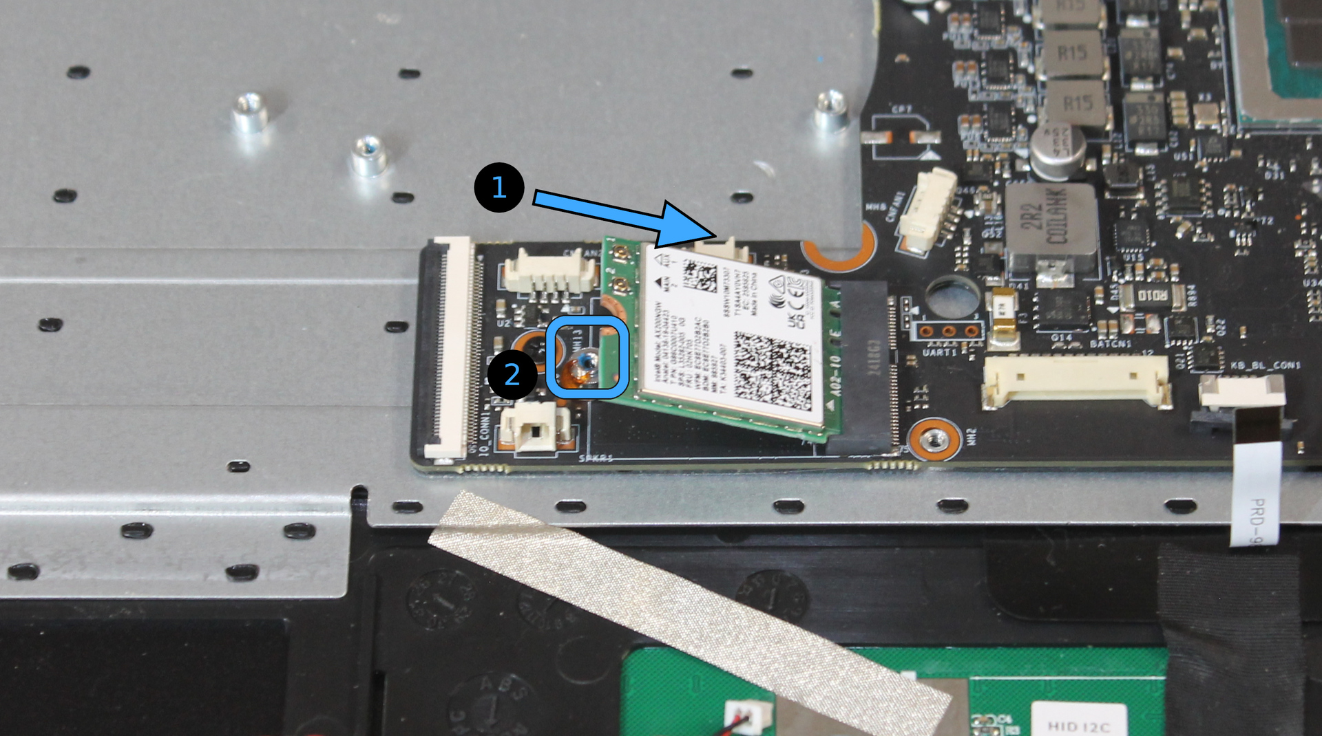
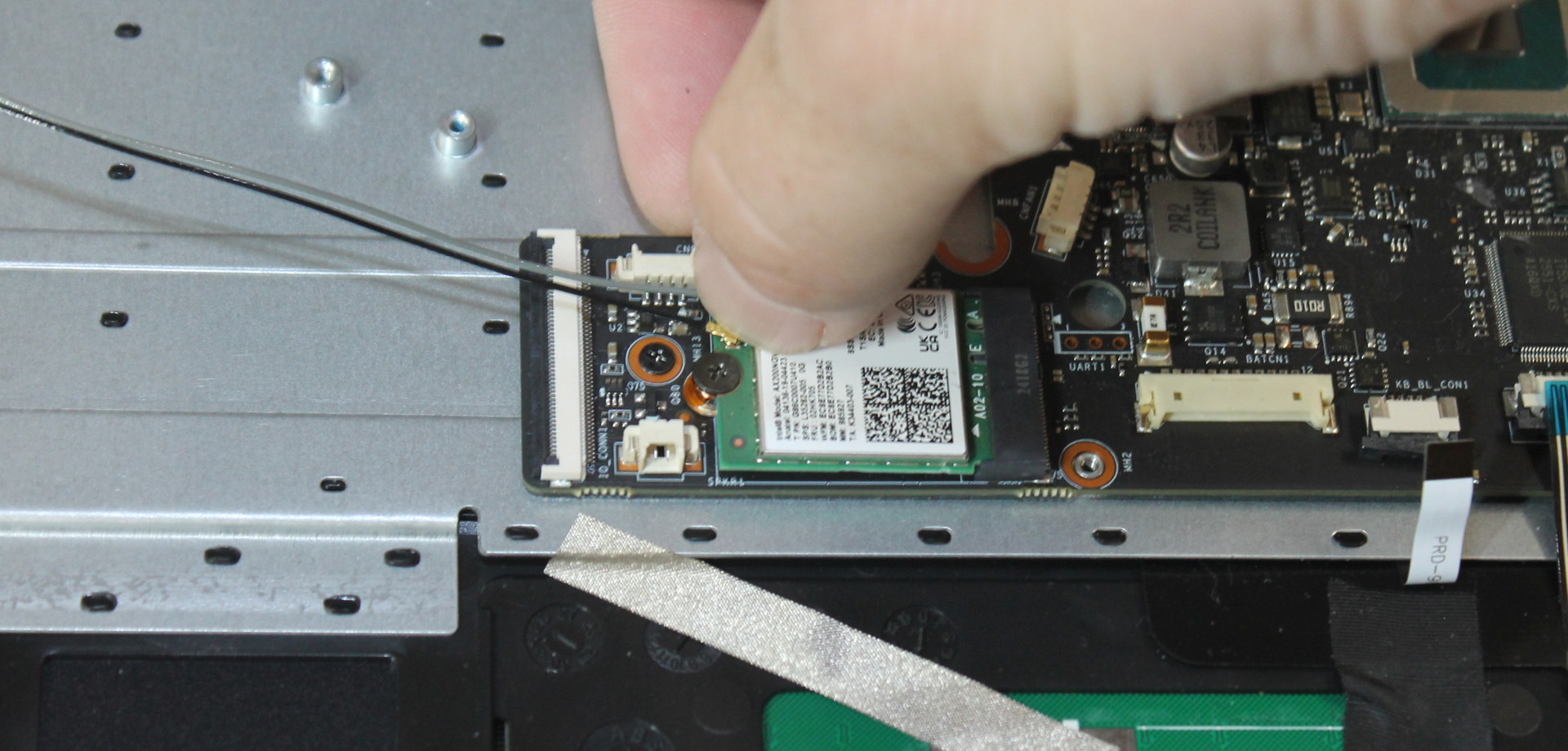
Position each coaxial cable connector over the socket, and gently press it down with a fingernail or plastic opening tool.
Important
Ensure the connector and socket are aligned properly. Attempting to press it down while misaligned may damage the connector or socket. Do not use tweezers, as they may prevent the connector from mating with the socket.
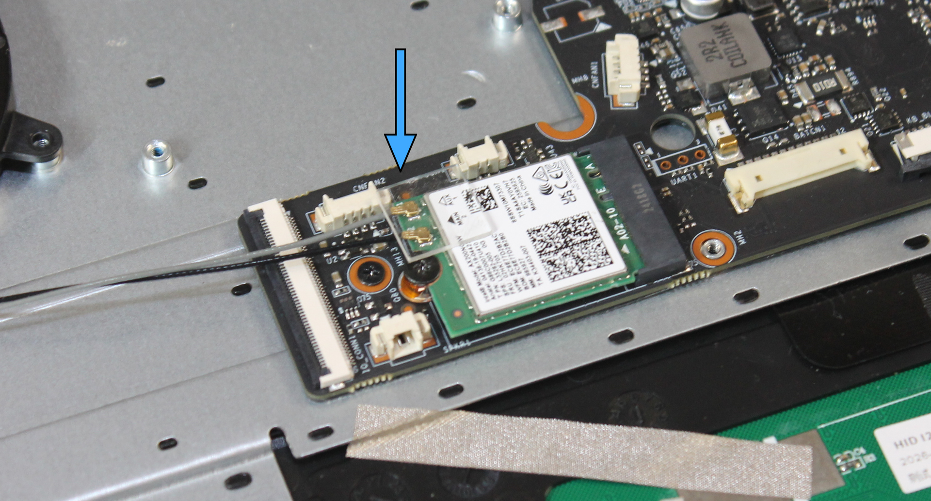
Press the coaxial cable retainer (plastic square) onto the wireless card to ensure the coaxial connectors remain in place.
Install fans#
Check the position of the wireless coaxial cables. The cable length varies slightly, so shorter cables can be positioned just under the corner of the left fan (there is sufficient clearance to install the fan over the cable). Longer cables can route around the fan as long as they are not under tension.
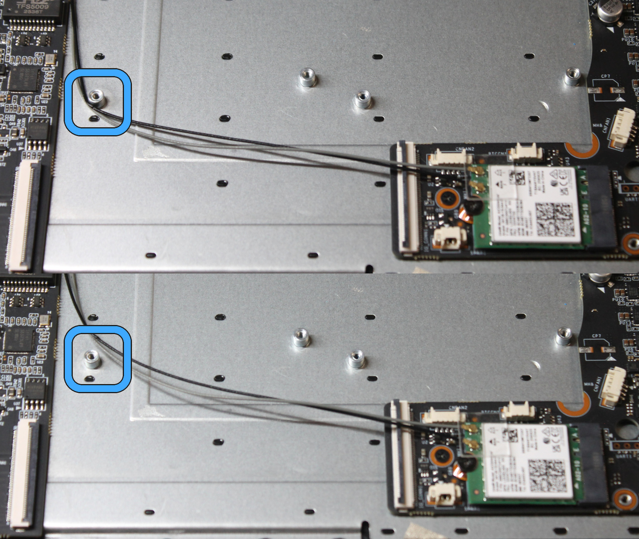
If one fan has a shorter cable, place it on the right, near the mainboard.
Place the other fan on the left.
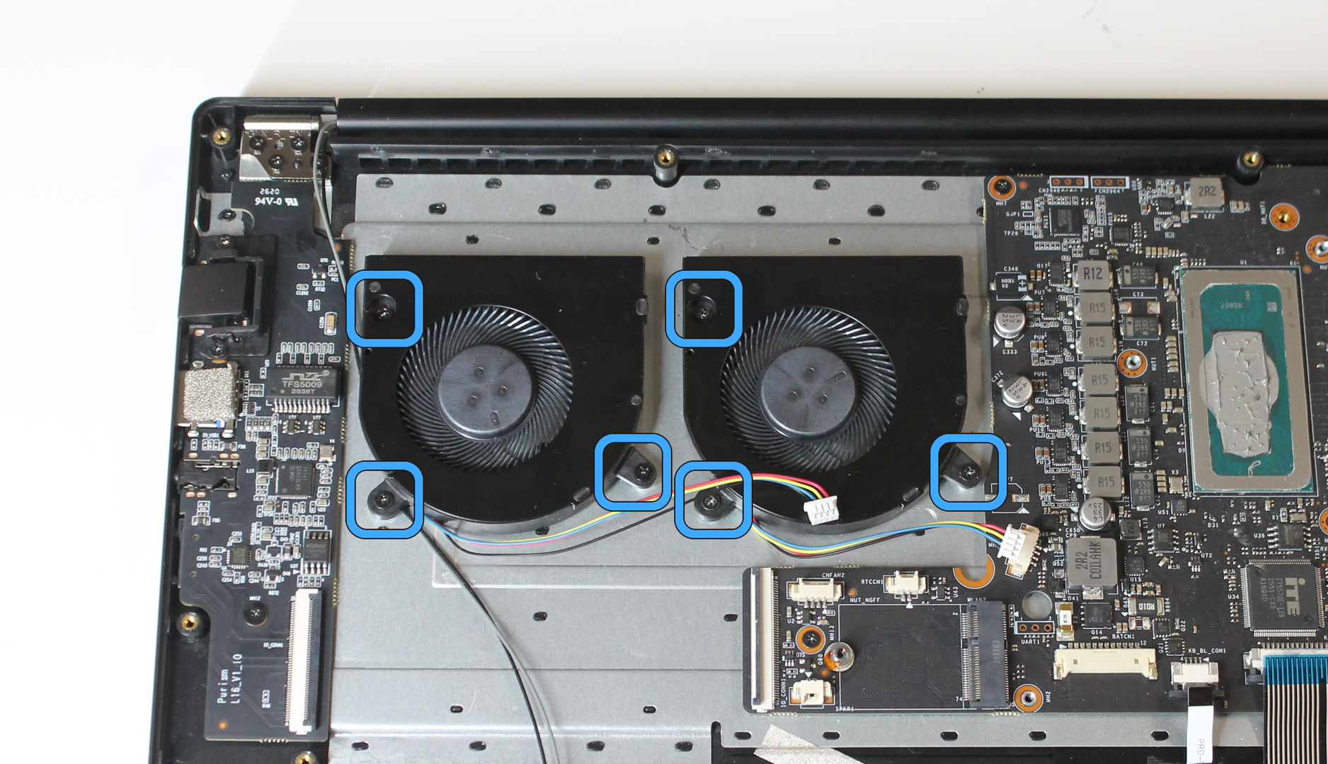
Secure each fan with 3 chassis screws.
Connect cables to mainboard#
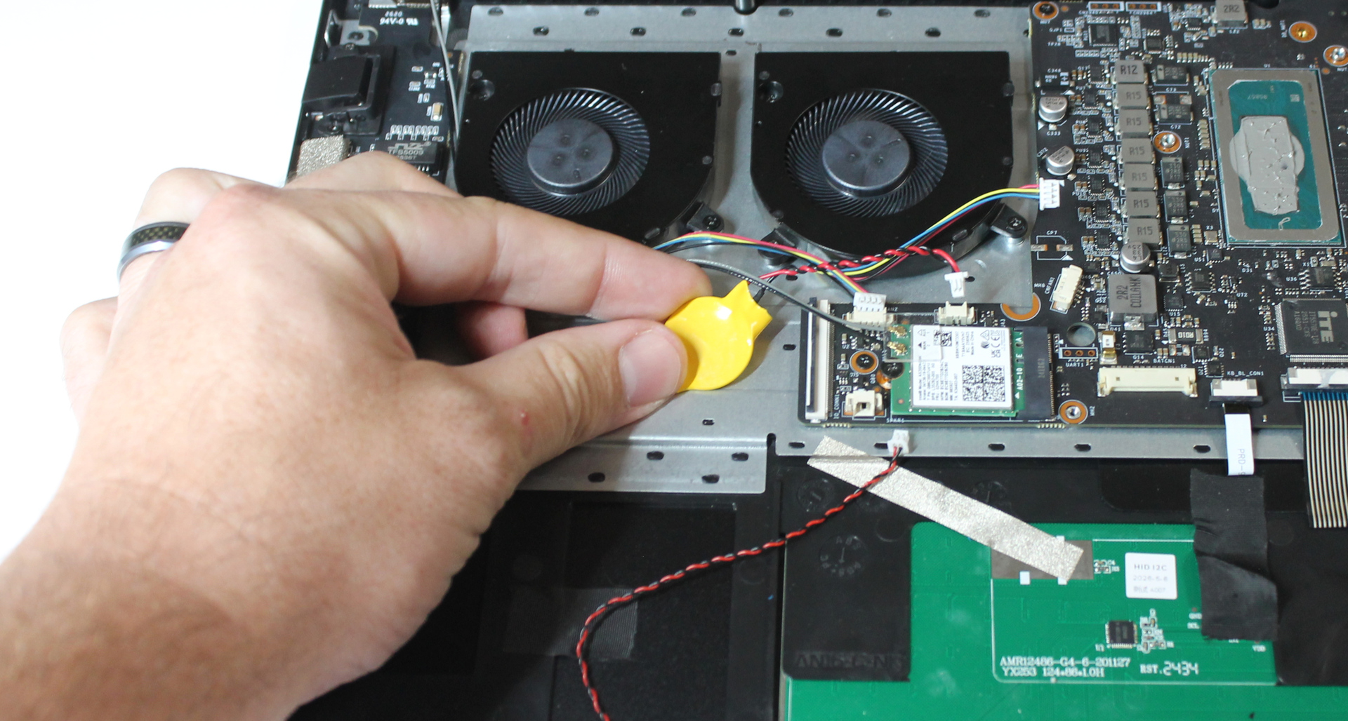
Stick the coin cell battery to the chassis below the fans, so it will be under the I/O cable.
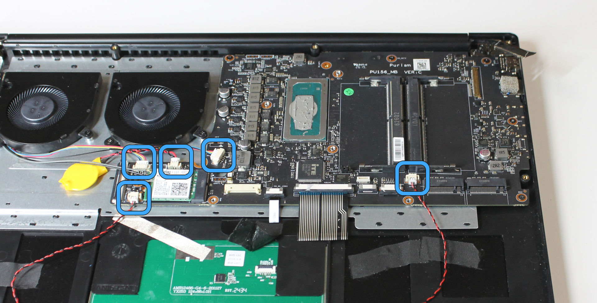
Connect the wafer connectors for each fan, each speaker, and the coin cell battery. Orient the connector correctly, and push the connector into the socket from each end.
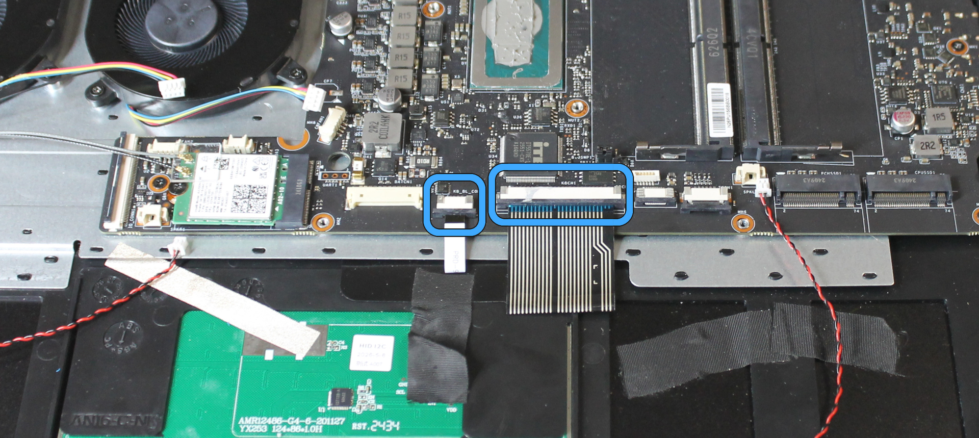
Connect the flat connectors for the keyboard and keyboard backlight. Slide the dark-colored retention slide downward from each end (if it is not already down). Insert the cable fully, with the electrical contacts facing the mainboard. Slide the retention slide upward from each end to secure the cable.
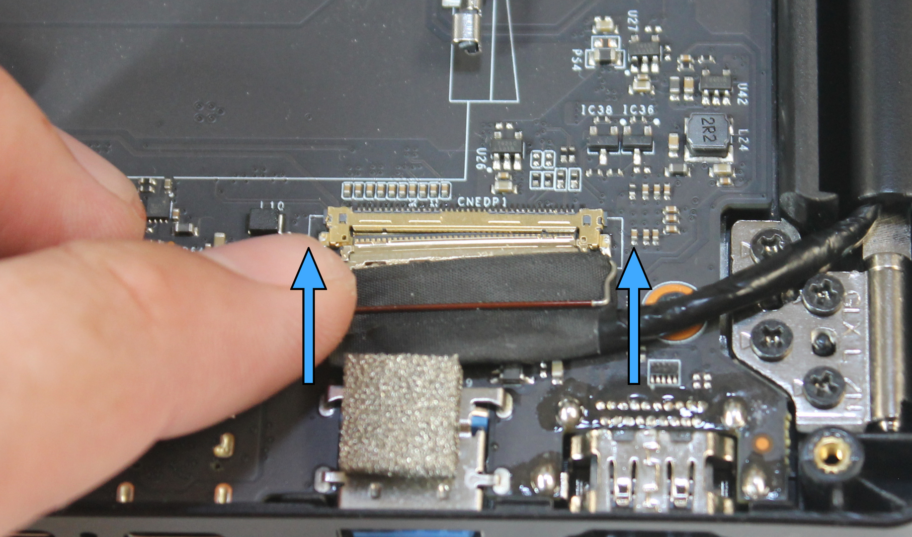
Lift the display connector retention lever, which is part of the connector (not the socket).
Insert the display connector into the socket fully by pressing on both ends.
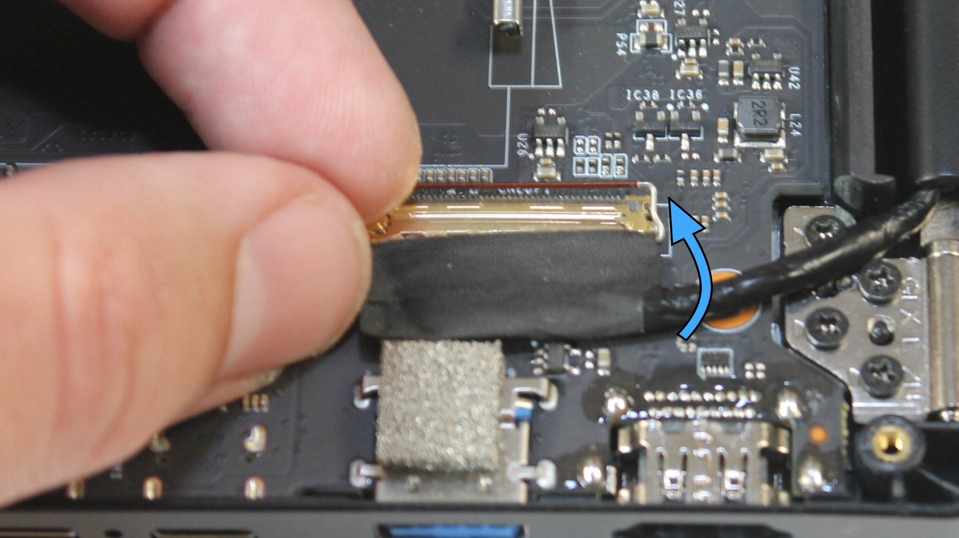
Lower the retention lever over the socket until it snaps into place.
Install heatsink#
If the heatsink thermal compound is clean, it can typically be reused 2-3 times. If not, replace the thermal compound.
To replace the thermal compound:
Clean the existing compound from the heatsink and CPU. Use 100% acetone or 91% isopropyl alcohol and a clean, lint-free cloth. Ensure all residual fluid evaporates.
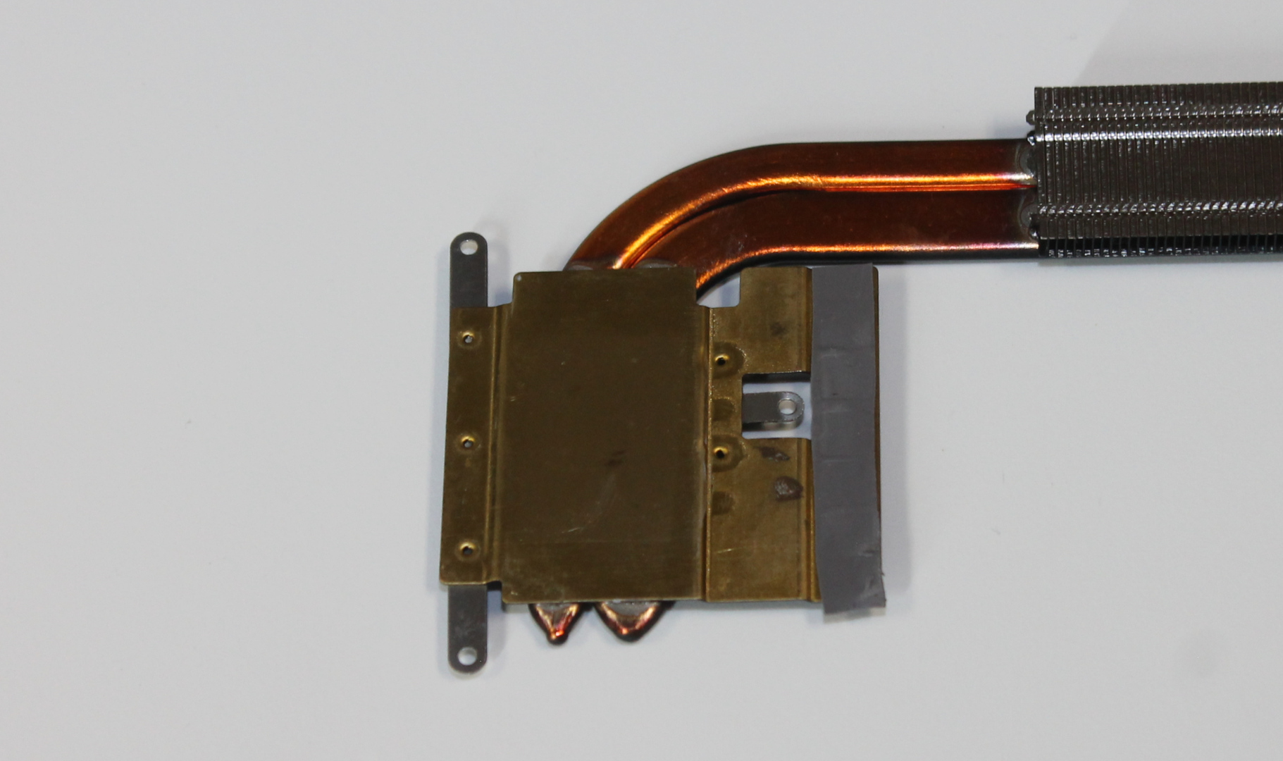
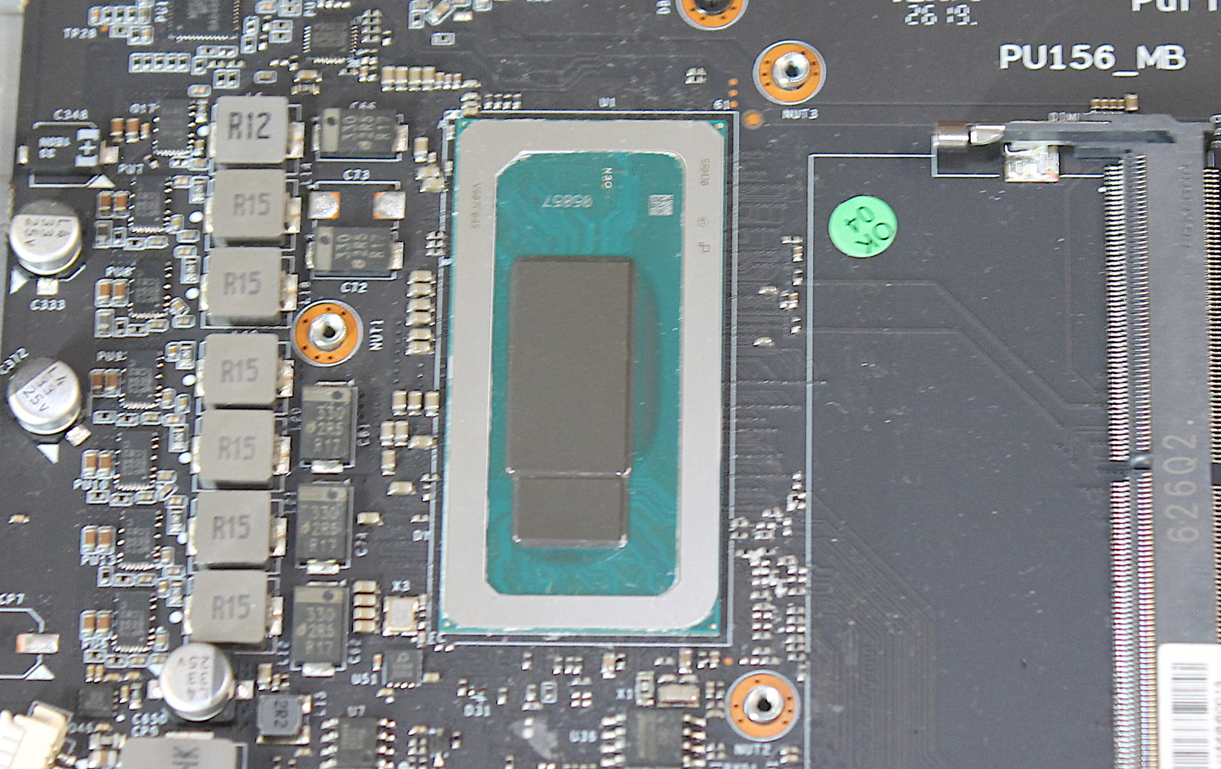
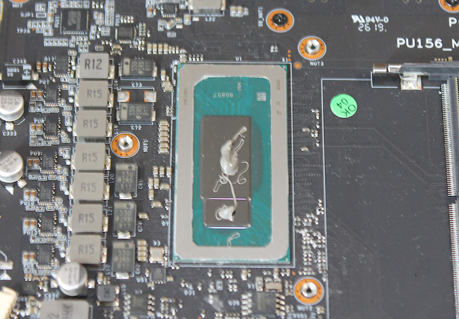
Place a bead of high quality thermal compound on the CPU and the PCH (Platform Controller Hub). The CPU is the larger die; place a bead about the size of a grain of rice. The PCH is the smaller die; place a smaller bead, about half the size used on the CPU. Do not use excessive thermal compound.
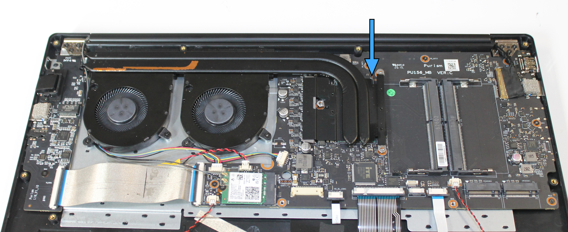
Place the heatsink directly onto the CPU. Avoid sliding or rotating it excessively to keep the thermal compound in place. If the placement was misaligned, consider replacing the thermal compound.
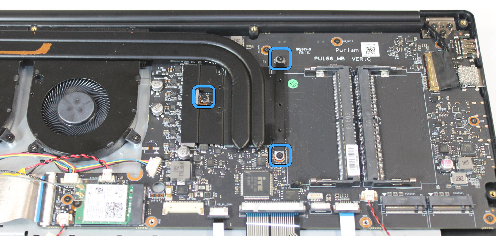
Install three mainboard screws, but do not tighten them fully yet. Turn the screws 1-2 times so they are seated in the threads, without placing uneven force on the CPU.
Tighten each screw a small amount further, then tighten each screw fully.
Tape the heatsink to the fans to help guide the airflow. If the tape removed in disassembly is in good condition, reuse it. If not, use a new piece of linen tape or Kapton tape.
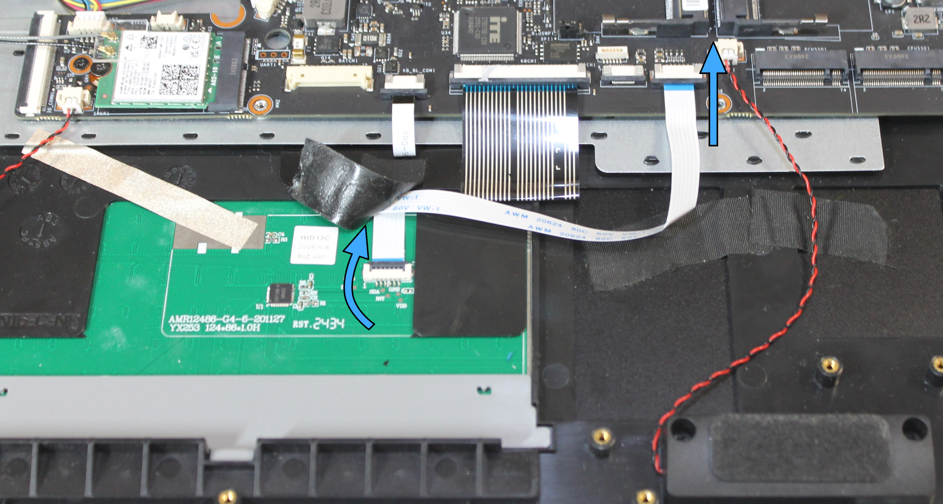
Install touchpad cable#
Raise the lever on the touchpad side connector by inserting a fingernail or plastic opening tool under the center of the lever, then gently pulling up.
Insert the touchpad cable fully, and lower the lever to secure it.
Release the mainboard side connector by sliding the dark-colored slide downward from each end.
Insert the touchpad cable fully, then raise the slide to secure it.
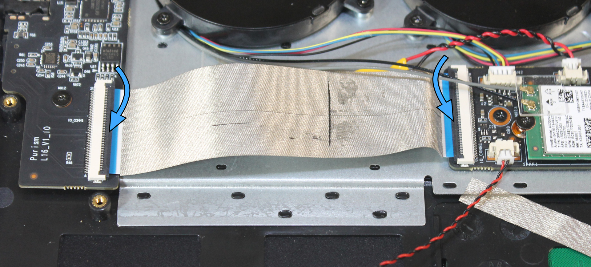
Install I/O cable#
Raise the levers on each I/O cable connector by inserting a fingernail or plastic opening tool under the center of the lever, then gently pulling up.
Insert the I/O cable fully into one connector, with the electrical contacts down, and lower the lever to secure it. The I/O cable can be installed in either orientation.
Repeat for the other connector.
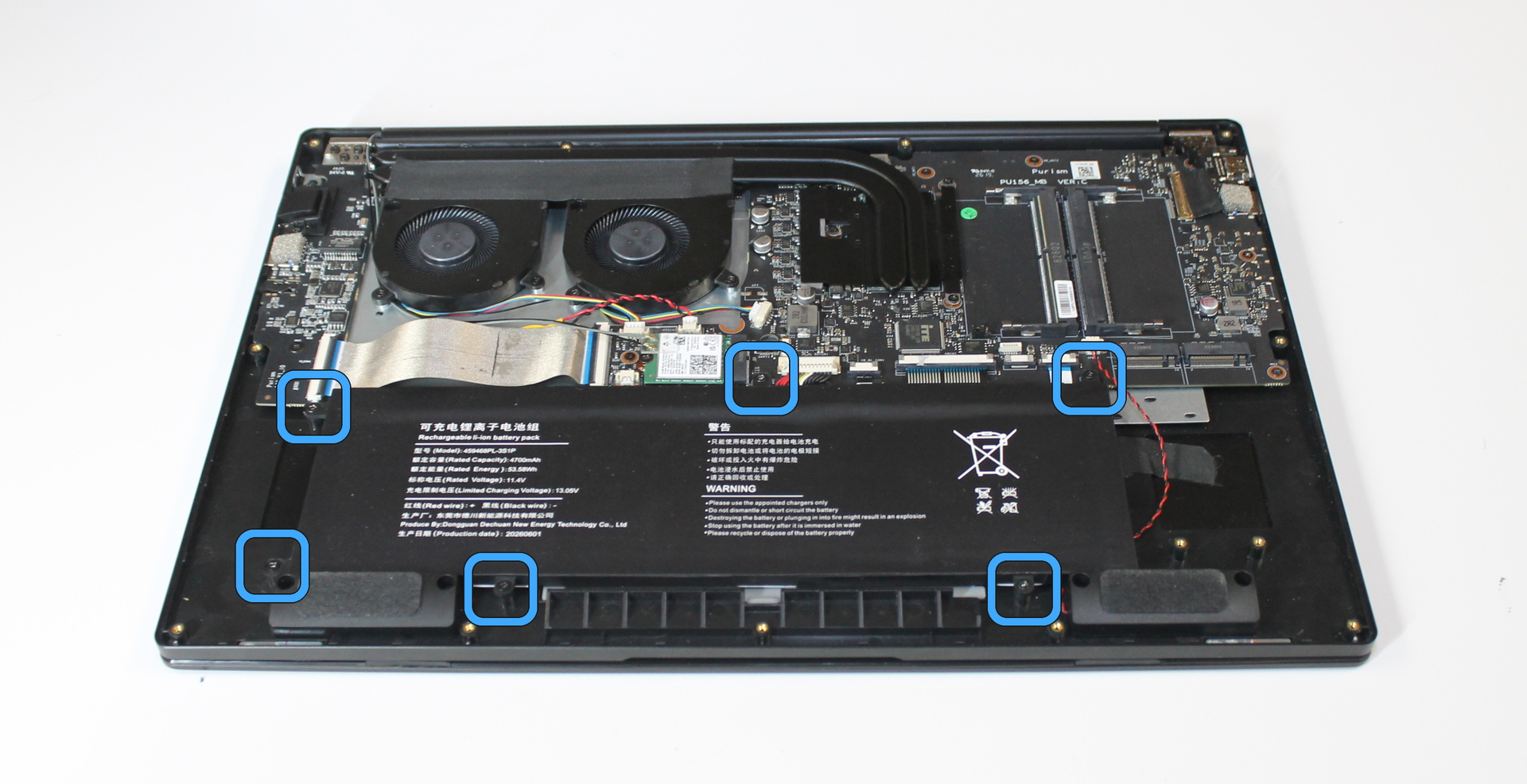
Install battery#
Place the battery over the battery screw holes. Do not connect the battery connector yet.
Install 6 chassis screws to secure the battery.
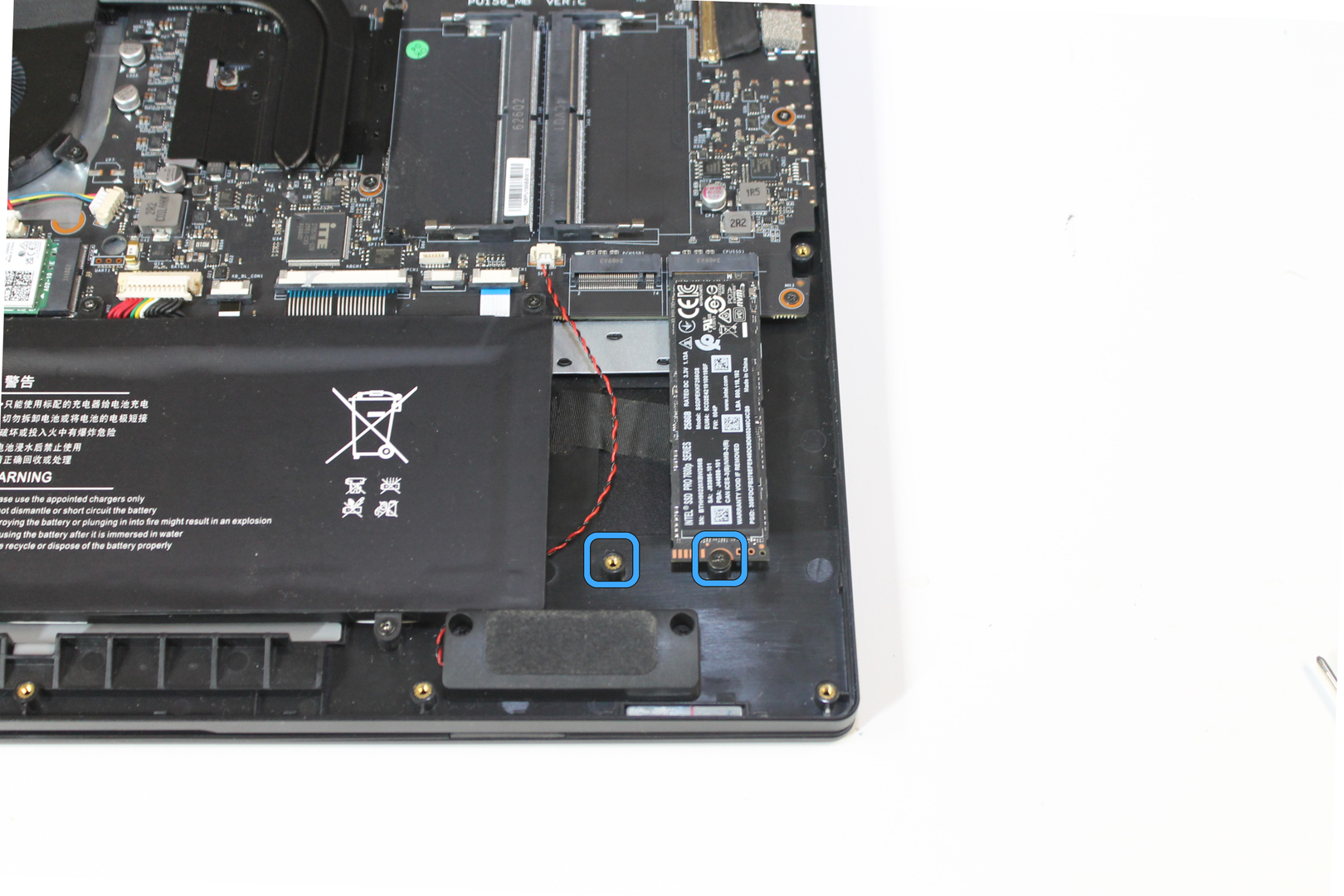
Install memory and storage modules#
Insert each storage module (SSD) into its socket, then lower it onto the screw hole.
Note
The two M.2 SSD sockets are labeled “CPUSSD1” and “PCHSSD1” on the mainboard. Either or both slots can be used; there is no “primary” slot. CPUSSD1 connects directly to the CPU and is faster for NVMe SSDs. Purism recommends installing your OS SSD in CPUSSD1.
Secure the SSD with a card screw.
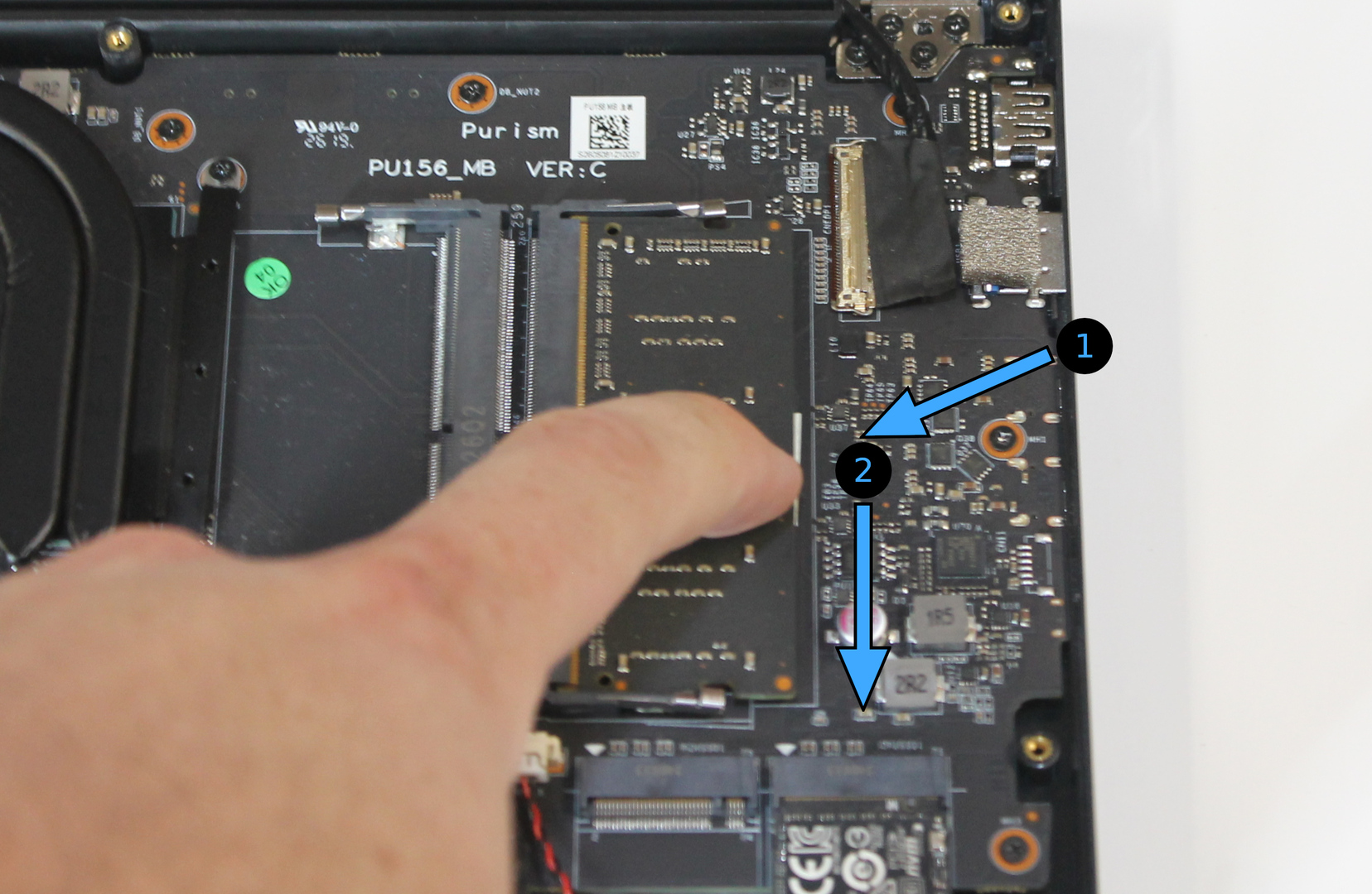
Insert each memory module (DIMM) into its socket, then lower to engage the retention levers until they click.
Note
Each DIMM socket is on a separate memory channel. You can use either socket or both, and there is no difference in performance.
Connect battery#
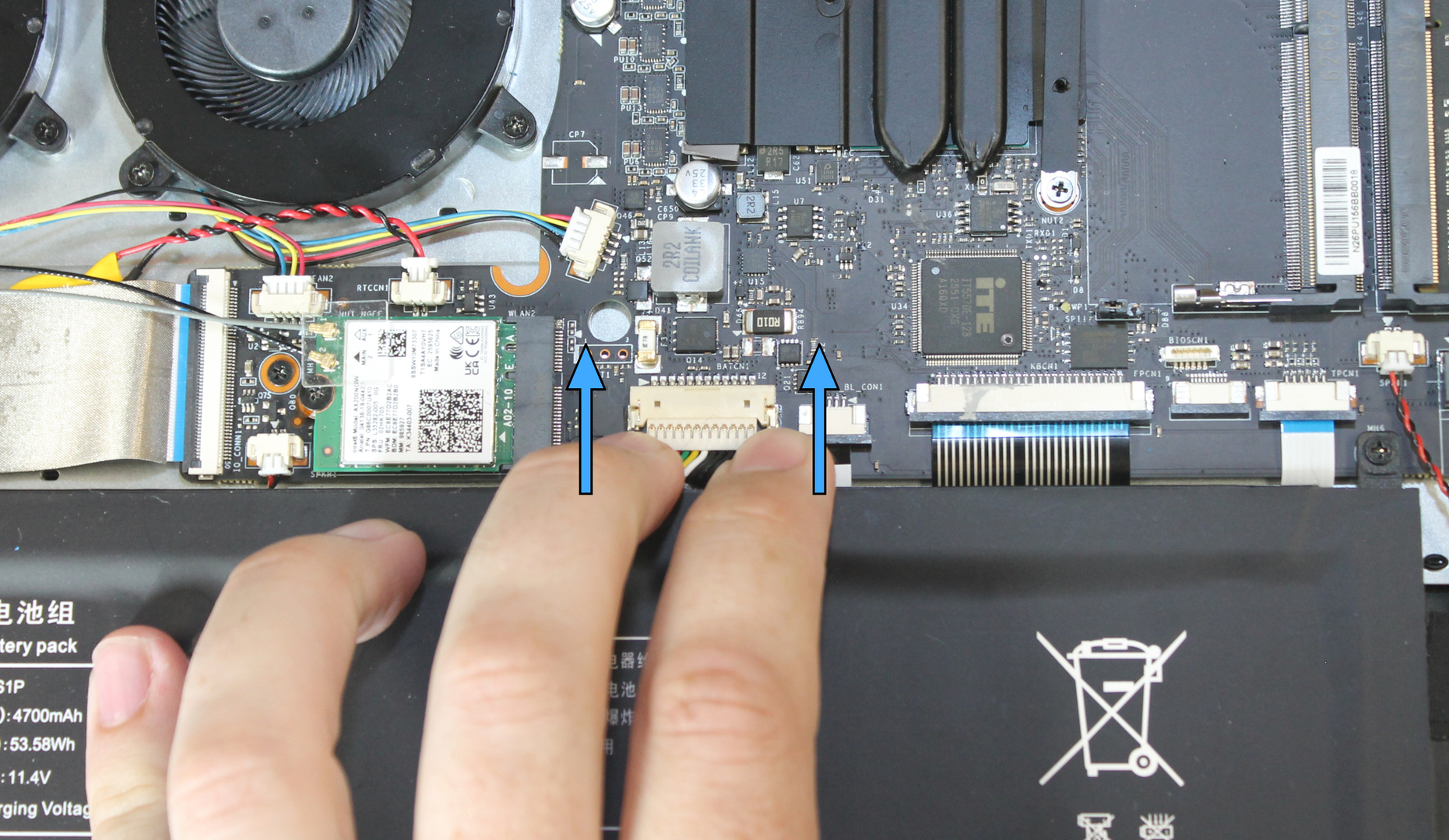
Insert the battery plug into the socket, ensuring that it is straight.
Press from both ends to insert the plug straight into the socket.
Install D-shell#
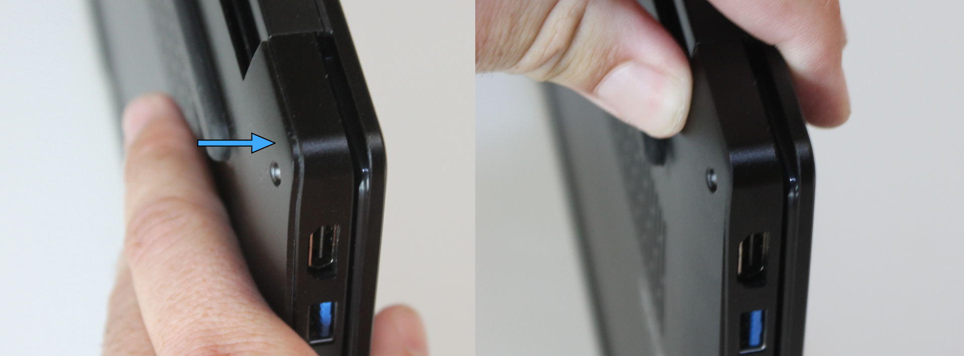
Place the D-shell onto the chassis.
Ensure all edges of the D-shell seat properly into the chassis. If they do not seat fully on their own, press down to flex the D-shell slightly until they do. The D-shell intentionally has a tight fit to keep it secured in place.
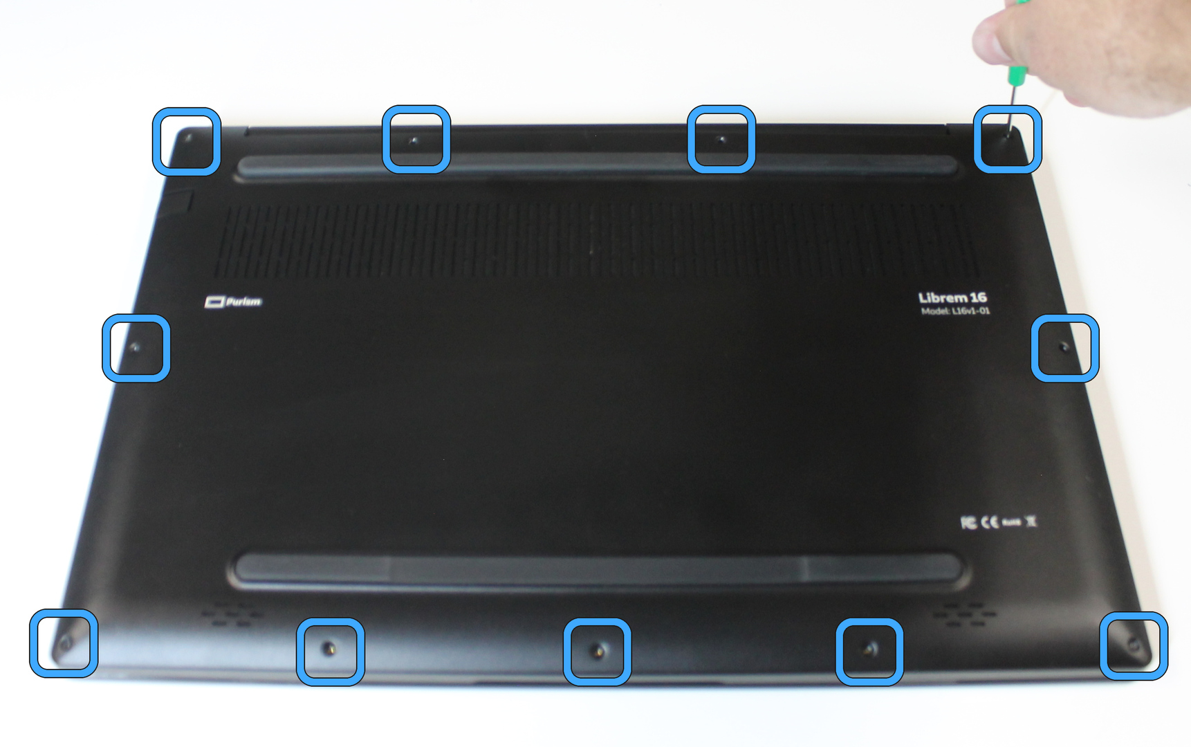
Install 11 bottom cover screws.