Serial Console
Preface
Debugging a Librem 5 that boots is pretty easy. Simply open a terminal or access the serial console over USB. However, if you are doing kernel development or porting alternative operating systems to the Librem 5, this may result in a Librem 5 that will not boot far enough to load regular diagnostic tools. When that happens, it’s time for raw serial access.
Download
Avoid boot loops: Try L5 over serial
Note
This article is written for the express purpose of interfacing with U-Boot’s shell. If you only need a Linux serial interface, you can instead use Serial over USB or SSH.
UART Interfaces For Debugging
The serial console on the Librem 5 can be used to interact with U-Boot and use its command line to alter boot parameters. There are four options to get at U-Boot’s serial shell:
- UART1 using the EXT CON Breakout Board which can be purchased on the EXT CON Breakout Board shop page. Removal of the M.2 cover and attaching/mounting this board is required.
Allows replacement of the back cover while the rigid-flex breakout board is installed inside the phone.
- UART2 using “thunderbolt alt mode” with the USB-C connector
Allows a U-Boot connection while the phone is fully assembled, without having to remove the back cover.
- UART1 from the Librem 5 test points
Requires opening and soldering to the main board.
- UART4 via the Librem 5 m.2 key E breakout board
Requires opening and replacing the wifi/bluetooth board.
EXT CON Breakout Board
The EXT CON Breakout Board (available on the EXT CON Breakout Board shop page) is a rigid-flex PCB which has standard 2.54mm (0.1”) pitched through-holes supporting the following signals:
UART1 RX/TX
SPI (3.3V logic)
I2C4 (1.8V logic)
- two GPIOs
1.8V logic for “NFC_EN”
3.3V logic for “NFC_IRQ”
1.8V
3.3V
GND
The Rigid section can be fastened down using the center screw that is typically used for the M.2 cover. Once this board is attached, it is thin enough to allow you to still place the back cover of the phone over it (so long as you don’t directly solder a header to it). Instead of soldering a header directly to the rigid section, you could instead use a press-fit header such as the Amphenol 93689-103-03LF. These will require that you cut off the excess length of the end that goes into the through hole, and pinch the remaining end with pliers so it fits well.
The benefit of using this board is that you will not have to modify the standard U-Boot in any way. You will also be able to access both U-Boot and Linux via the RX/TX & GND pins using a standard 3.3V FTDI USB debug cable such as the FTDI TTL-232R-RPI.
The Panasonic AXT624124 connector that’s found on the rigid-flex board can be obtained via Digikey or Mouser.
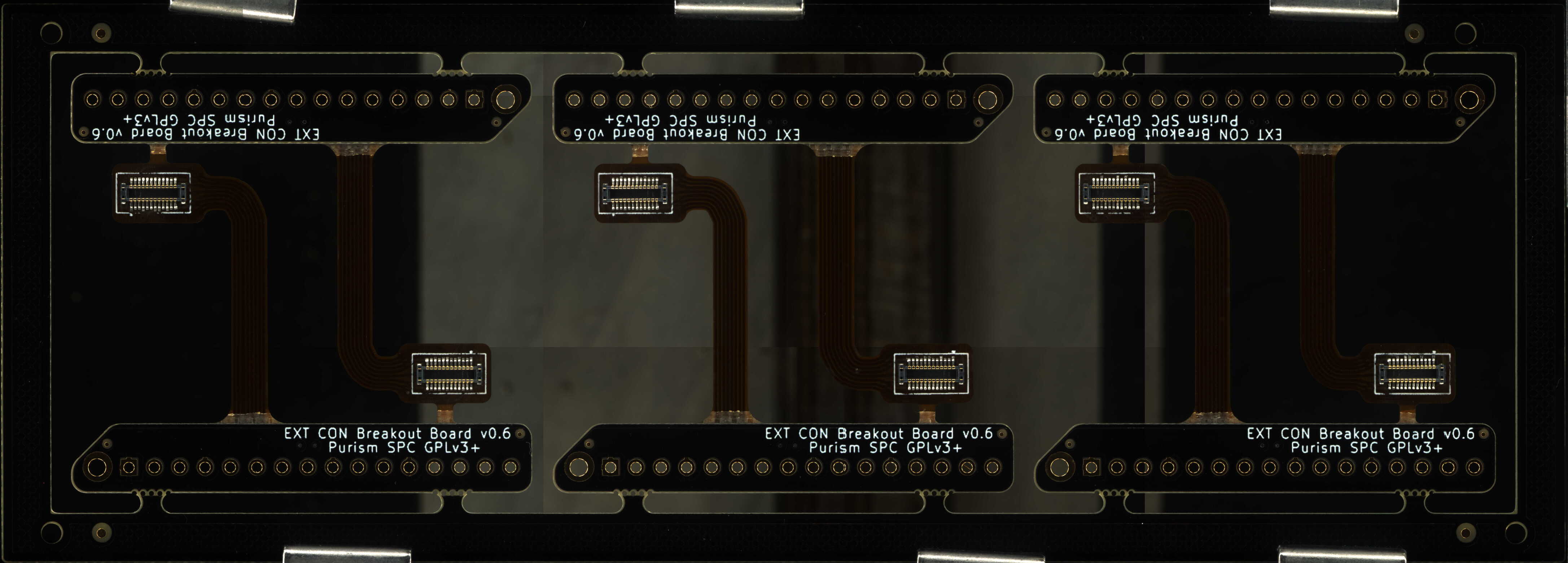
Here is a panel of the v0.6 rigid-flex board (made by PCBWay, 1.2mm thick rigid section):
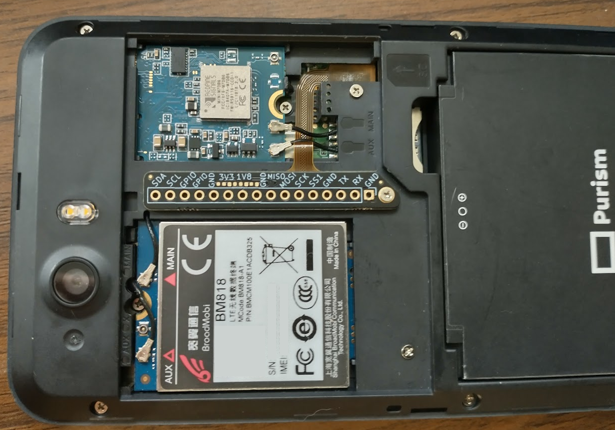
Here is a photo of v0.5 installed in a Librem 5 (edited to correct 1V8 & 3V3 silkscreen markings):
Warning
v0.5 WARNING: The EXT CON Breakout Board v0.5 silkscreen markings for 1V8 and 3V3 are mistakenly swapped. The photo above was edited to correct for this mistake. v0.6 and all future versions have corrected this silkscreen error.
“Thunderbolt Alt Mode” For MUXing UART Onto USB-C SBU Pins
Note
An alternative method to the ones described here would be to use debubo or sbub with a serial-to-USB adapter.
In thunderbolt alt mode, the L5’s TPS65982 chip muxes the serial lines to the SBU pins of the USB-C port. To make the TPS65982 chip multiplex the UART2 RX & TX to the USB-C SBU pins, it needs a thunderbolt hub/dock connected to enter thunderbolt alt mode. The hub/dock is not needed otherwise even though it can provide power to the Librem 5. The TPS65982’s thunderbolt alt mode is required for multiplexing its LSX (UART2) pins to the SBU pins. The Librem 5 does not actually support the thunderbolt alt mode; this is only used for debugging purposes.
A breakout cable or board is required for access to the serial lines muxed to the USB-C SBU lines. Data lines, power and CC lines get passed through between the L5 and the hub/dock.
Since the serial lines that are multiplexed are UART2 and at time of writing U-Boot uses UART1 by default a version of U-Boot is needed that uses UART2 and sets the “Intel VID Configuration” register upon boot.
The serial IO starts just after the SPL (Secondary Program Loader) loads and then the TPS65982 can perform the multiplexing.
Solderless Case-Closed Solution (Serial Adapter Embedded): USB Cereal
Note
See this section
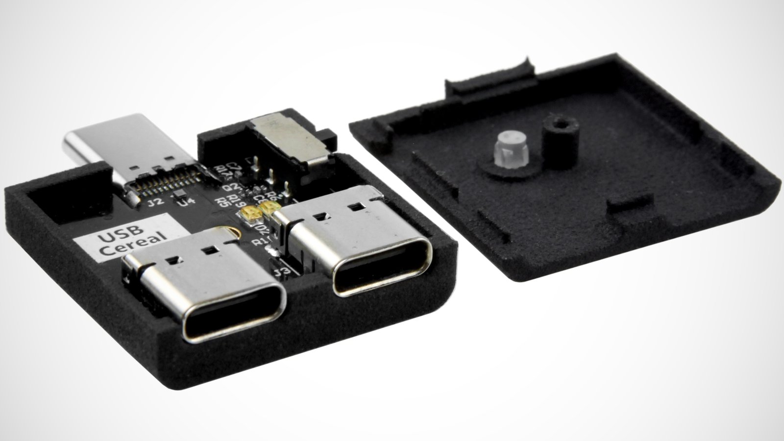
A device called USB Cereal is available on Crowd Supply which can be used in place of a breakout board and FTDI cable. It does not require any soldering and is a tidier solution.
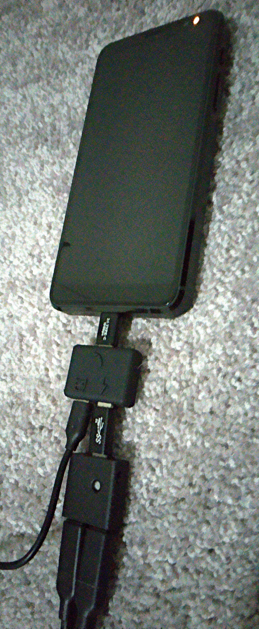
Photos Of Everything Connected
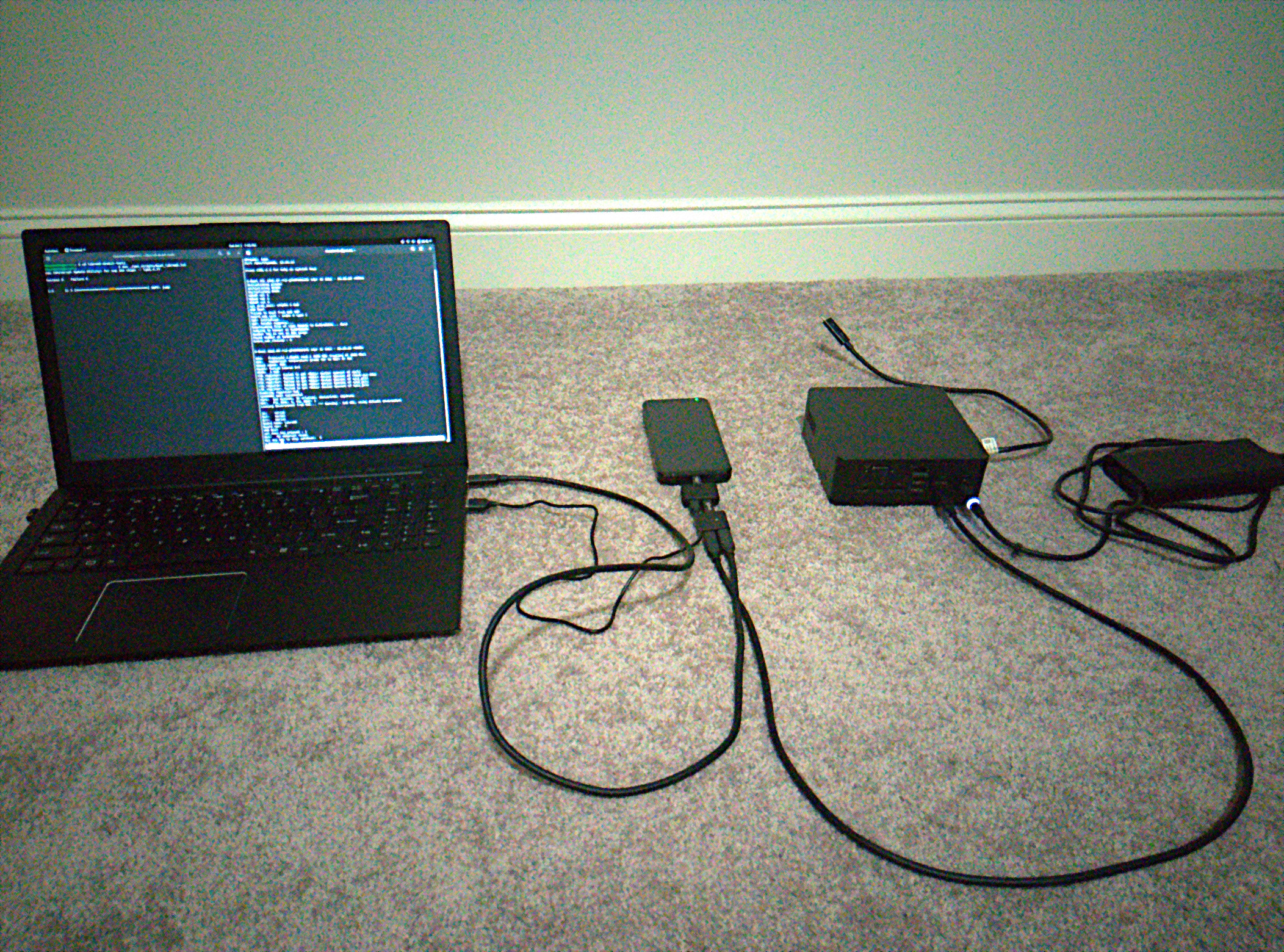
Here’s what it looks like when everything is connected and working:

The USB Cereal CAD files are freely available.
Known Working Thunderbolt Hubs/Docks
Dell TB16
In addition to the thunderbolt hub/dock, you will need a Dell AC adapter. Unfortunately, Dell uses the 1-wire protocol to identify the charger, which means it will reject generic ones even if they fit the receptacle.
This adapter allows the phone to stay charged while in the multiplexed debug mode. The following AC adapters have been used:
Dell DA180PM180
Dell DA130PE1-00
Energy4U 90W-PA05
Do not use the pigtail USB-C cable that is attached to the thunderbolt hub/dock. Instead, you’ll need to use your own USB-C cable with the which has a thunderbolt icon above it (the only USB-C port on the hub/dock). It will not work with the cable that comes out of the hub/dock.
How to check whether a Hub/Dock might work
Note
Work in progress.
Use i2ctransfer to look at the registers (e.g. see section Standard U-Boot Just Using UART2)
Required Custom U-Boot
Standard U-Boot Just Using UART2
Once you have a working thunderbolt hub setup, the simplest method for accessing U-Boot is to temporarily boot a U-Boot which uses UART2 instead of UART1 as its serial interface.
Before booting via this U-Boot, you will need to login into Linux and run the following commands while the thunderbolt hub is attached:
$ sudo i2ctransfer -f -y 0 w10@0x3f 0x52 0x08 0x03 0x02 0x00 0x00 0x00 0x00 0x02 0x05
$ sudo i2ctransfer -f -y 0 w6@0x3f 0x08 0x04 0x48 0x52 0x53 0x54
$ sudo reboot
The second i2ctransfer command here issues a hard reset of the TPS65982 USB-C PD controller. When this step is executed, a battery must be inside the phone to allow it to stay powered. The thunderbolt hub must continue to be attached to the phone during the entirety of the reboot and while the serial interface is being used. If you were to execute these commands without the thunderbolt hub attached then the TPS65982 will re-read the firmware from the SPI NOR flash and reset all of its registers, including 0x52 which you changed here.
Before rebooting, you may also want to check to make sure it actually entered thunderbolt alt mode by reading register 0x59 and looking at bit[1] (it is represented in little-endian):
$ sudo i2ctransfer -f -y 0 w1@0x3f 0x59 r14
0x0d 0x03 0x00 0x00 0x00 0x00 0x01 0x00 0x02 0x00 0x00 0x00 0x00 0x00
After confirming that the thunderbolt alt mode has been entered, the volume up button should be held while rebooting the phone in order to enter serial download mode to boot the UART2 U-Boot.
U-Boot Which Triggers a TPS65982 Hard Reset
You could also use this U-Boot which configures a TPS65982 register to allow it to enter thunderbolt alt mode, performs a hard reset of the TPS65982 after that, and uses UART2 instead of UART1 as its main serial debugging interface.
Warning
About Usage Without a Battery
Using this special U-Boot means you will not be able to power the phone from only USB power, unlike the standard U-Boot which will allow you to boot the phone without a battery. This is because U-Boot is intentionally causing the TPS65982 to reset after writing the Intel VID Configuration register which allows it to support the thunderbolt alt mode with existing firmware.
If you require that the phone boots without a battery, does not require booting into Linux first, and still do this debugging then you can need to modify the TPS65982 firmware to enable thunderbolt alt mode, write it to the SPI NOR flash using the write-flash.sh script in the librem5-devkit-tools repo, and modify the standard U-Boot to use UART2 instead of UART1 (if this isn’t already done).
To enable thunderbolt alt mode, register 0x52 of the TPS65982 should be set to 0x0502000000000203, using i2ctransfer you should get the following when this is done correctly:
$ sudo i2ctransfer -f -y 0 w1@0x3f 0x52 r9
0x08 0x03 0x02 0x00 0x00 0x00 0x00 0x02 0x05
You will know that it is in thunderbolt alt mode when bit 1 (ThunderboltModeActive) of the “Intel VID Status” register is 1:
$ sudo i2ctransfer -f -y 0 w1@0x3f 0x59 r14
0x0d 0x03 0x00 0x00 0x00 0x00 0x01 0x00 0x02 0x00 0x00 0x00 0x00 0x00
You will know that the LSX (UART2) pins are being multiplexed to the SBU pins when bits[16:14] = 110 in the “Mux Status (Debug)” register, for example:
$ sudo i2ctransfer -f -y 0 w1@0x3f 0x6e r9
0x08 0x00 0x80 0x1f 0x47 0x01 0x00 0x00 0x00
Which in binary is (bolded are bits[16:14]):
0000 0000 0000 0000 0000 0000 0000 0001 0100 0111 0001 1111 1000 0000 0000 0000
This specifies that the SBU crossbar multiplexer is configured to “LSX_P2R to SBU2, LSX_R2P to SBU1”.
Booting And Accessing A Custom UART2 U-Boot via UUU With USB Cereal (no soldering required)
Required Materials
- Librem 5 with the TPS65982 firmware written to the SPI NOR flash (using firmware-tps6598x-nonfree and write_flash.sh)
This SPI NOR flash firmware already comes standard with all L5 phones that are shipped; you likely don’t need to do anything
Thunderbolt dock / hub (e.g. Dell TB16)
AC adapter (e.g. Dell DA180PM180)
USB-C “Extension Coupler Adapter” Set (male-male and female-male are required), these are know to work
One USB-C to USB-C cable
One USB-C cable to Type-A cable (will go to your computer, so it could also be USB-C to USB-C)
One MicroUSB cable with a small plastic housing section
Grab the required files from here
Connecting Everything
Connect the AC adapter to the thunderbolt dock and a wall outlet
Place the phone into SDP mode (this can easily be achieved by removing the battery, holding the vol+ button, and reinserting the battery)
Attach the one end of the USB-C male-male adapter to the phone and the end to the port on the USB Splitter with the phone symbol
Flip the switch on the USB Cereal to its 3.3V position
Connect the female-male USB-C adapter to the male plug (J2) on the USB Cereal, making it slightly extended
Connect the extended male plug on the USB Cereal to the USB-C port on the USB-C Splitter with the lightning bolt symbol
Attach one end of the USB-C to USB-C cable to the USB-C port on the thunderbolt dock, and the other end to the passthrough port (J1) on the USB Cereal (do not use the captive cable that is permanently attached to the dock, it doesn’t work)
Connect the remaining port on the USB Cereal (J3) to the host computer, this will give you access to the i.MX8M’s UART2
Connect a MicroUSB cable from the USB C Splitter (little robot symbol on the plastic) to the host computer, this will give you access to the USB 2.0 D+/D- interface of the phone (e.g. for uuu)
Using UUU to Temporarily Boot U-Boot With UART2 Serial Access
cdinto thelibrem5-devkit-toolsdirectory (or the directory containing these files from Nextcloud)In a separate terminal, open a minicom session using the serial to USB device (e.g. USB Cereal),
minicom -D /dev/ttyUSB0In the original terminal, run
uuu ./uuu_scripts/boot_librem5.lst(this is a custom u-boot that will configure the TPS65982 to allow it to multiplex UART2 to the SBU pins when a thunderbolt device is attached)You should now be in U-Boot; no soldering required!
Notes
The
boot_librem5.lstuuu script comes from the librem5-devkit-tools repo and should be obtained from that repo to make sure it’s up-to-date- The file
files/u-boot-librem5.imxcame from theupstream/librem5-uart2branch in angus.ainslie/uboot-imx (SHA256 705d214ce9afa23d34dcfdf70f9a3a043b6b8f5c93f5ec72f334ab234e5cafa4) It is suggested to obtain the latest build available
- The file
files/Imageandfiles/imx8mp-librem5.dtbare just empty binary files (1 byte in size) and are just present for the uuu script to work
Booting And Accessing A Custom UART2 U-Boot Via UUU With USB-C Breakout Board (soldering required)
Required Materials
Thunderbolt Hub/Dock (e.g. Dell TB16, report known-working hubs/docks not yet mentioned in Known Working Thunderbolt Hubs/Docks)
AC Adapter (e.g. Dell DA180PM180)
USB-C Male to Female Breakout Board
TTL UART/Serial to USB Debug Cable (e.g. FTDI TTL-232R-RPI)
Three (3) Breakaway Molex Male Through-Hole Header Pins (e.g. 90120-0762)
USB-C to USB-C Cable (pretty much any will work, like the cable that came with the phone)
Breakout Board Solution
If the “USB Cereal” device is not used, then another option is to use a breakout board.
It is best to connect this breakout board at the thunderbolt hub end since you can simply plug and unplug a USB-C cable coming from this breakout board rather than plugging and unplugging the breakout board to/from the phone, which would have a risk of breaking.
Simpler Way
The following USB-C male to female breakout board can be used:
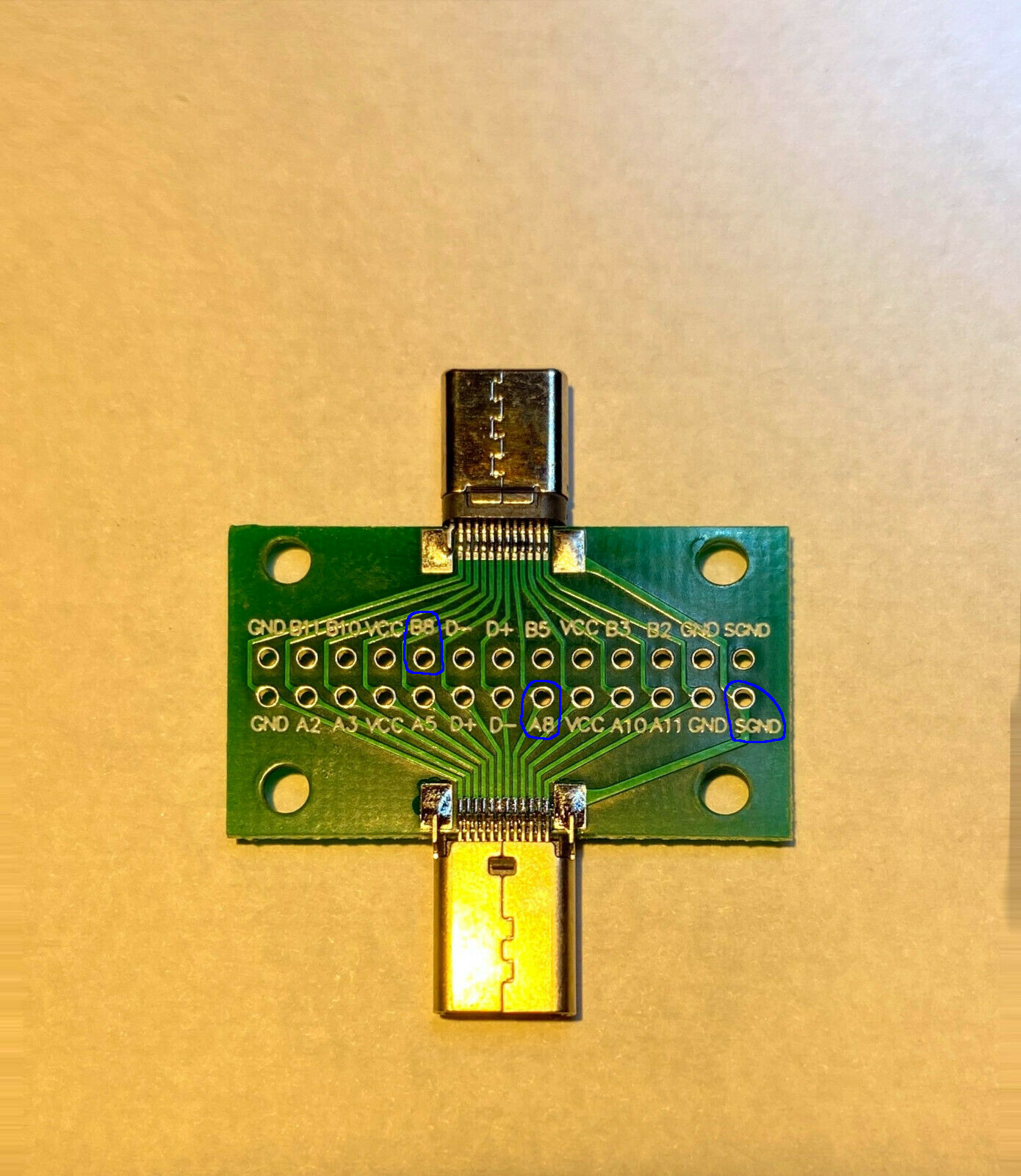
Along with three (3) breakaway Molex male header pins, separated into single individual pieces: https://www.mouser.com/ProductDetail/Molex/90120-0762?qs=NKHyz0HolODkarWFh2VFww%3D%3D
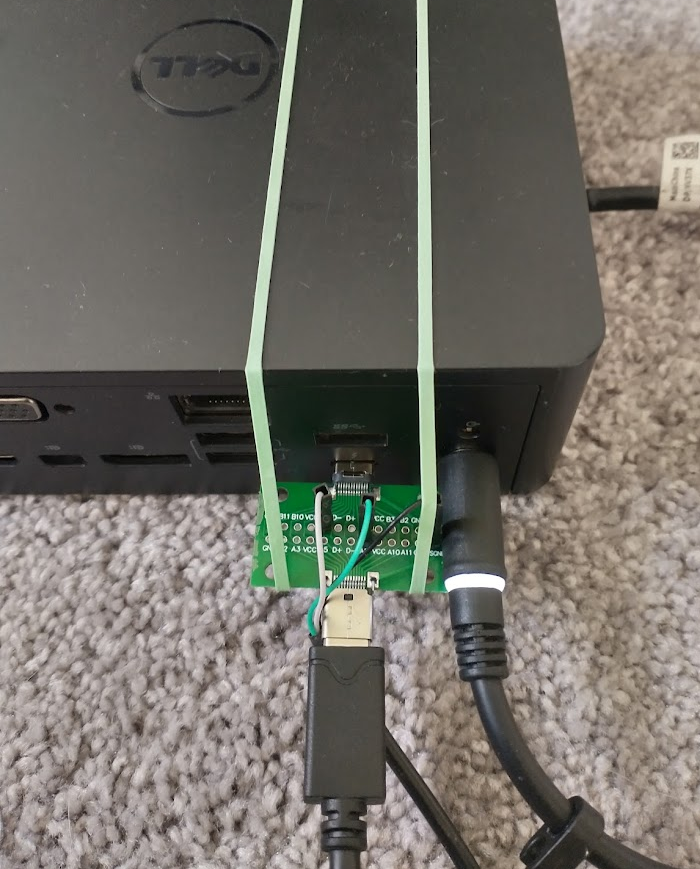
Solder these three breakaway Molex pins on the holes labeled A8, B8, and SGND as marked in the image above.
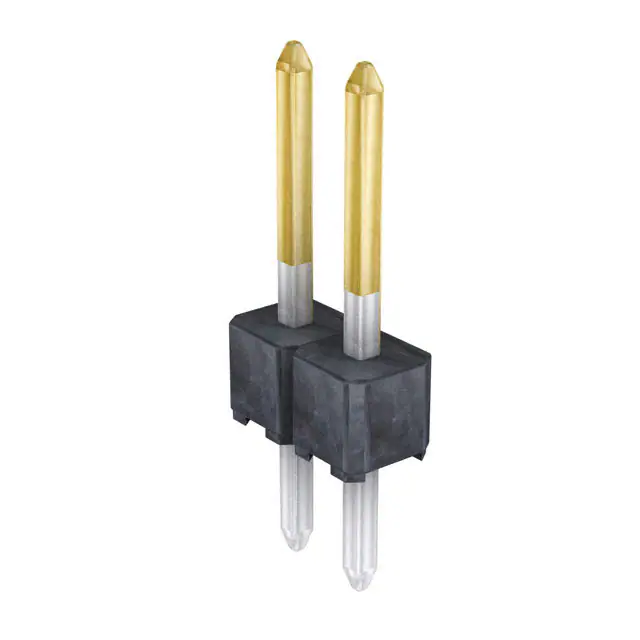
Attach the usb serial with ground to SGND, with RX to A8 (TX of the phone), and with TX to B8 (RX of the phone).
Here is an example where rubber bands are used to keep the breakout board secure to the hub:
Alternate Breakout Board Solution (more soldering required)
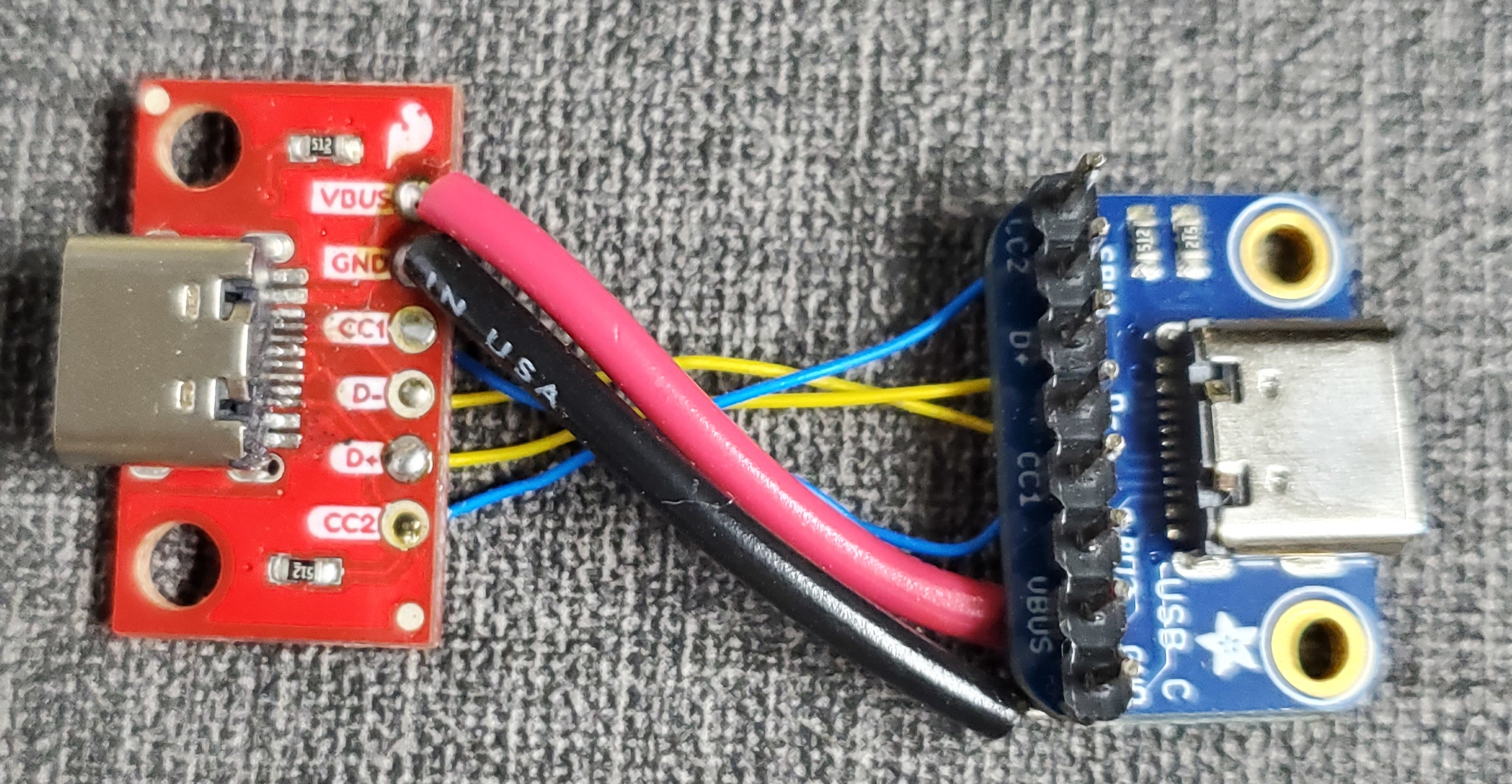
Front and back of the “break out” board. Blue Adafruit board is connected to the L5 and red Sparkfun board to the thunderbolt hub.
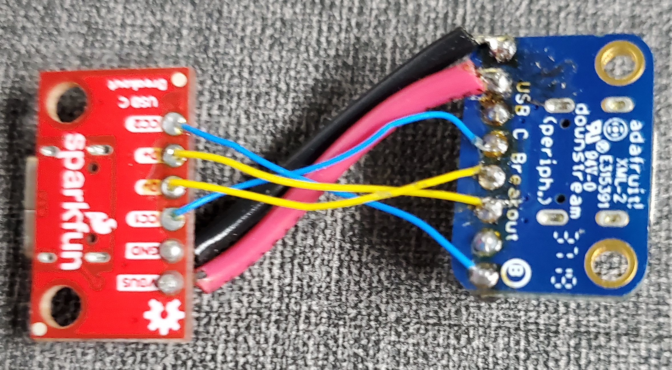
Using the FTDI cable mentioned earlier, attach the black wire to GND, the yellow wire (RX of the cable) to SBU1 (TX of the phone), and the orange wire (TX of the cable) to SBU2 (RX of the phone) of the Adafruit breakout board:
Serial Connection
The baud rate is 115200 8N1. If using minicom, make sure to disable hardware flow control; otherwise it will not accept input.
Serial Adapters
Any 3.3V TTL UART to USB adapter with support for the operating system you’ll use for the terminal program to connect to the serial console that can do 115000bps will probably do.
If you used one successfully and its not mentioned here, please let us know to have it added or add it yourself.
FTDI 3.3V TTL UART to USB debug cable sold by Mouser
https://www.mouser.com/ProductDetail/FTDI/TTL-232R-RPI?qs=3tuk1l7PSbNqj0mOeA5IPw%3D%3D

Pin-out:
black = GND/ground
yellow = RX/receive
orange = TX/transmit
UART1 Test Points on the Main Board
For Librem 5 test points for Evergreen, use UART1_TXD, UART1_RXD and GND.
M.2 Key E breakout board
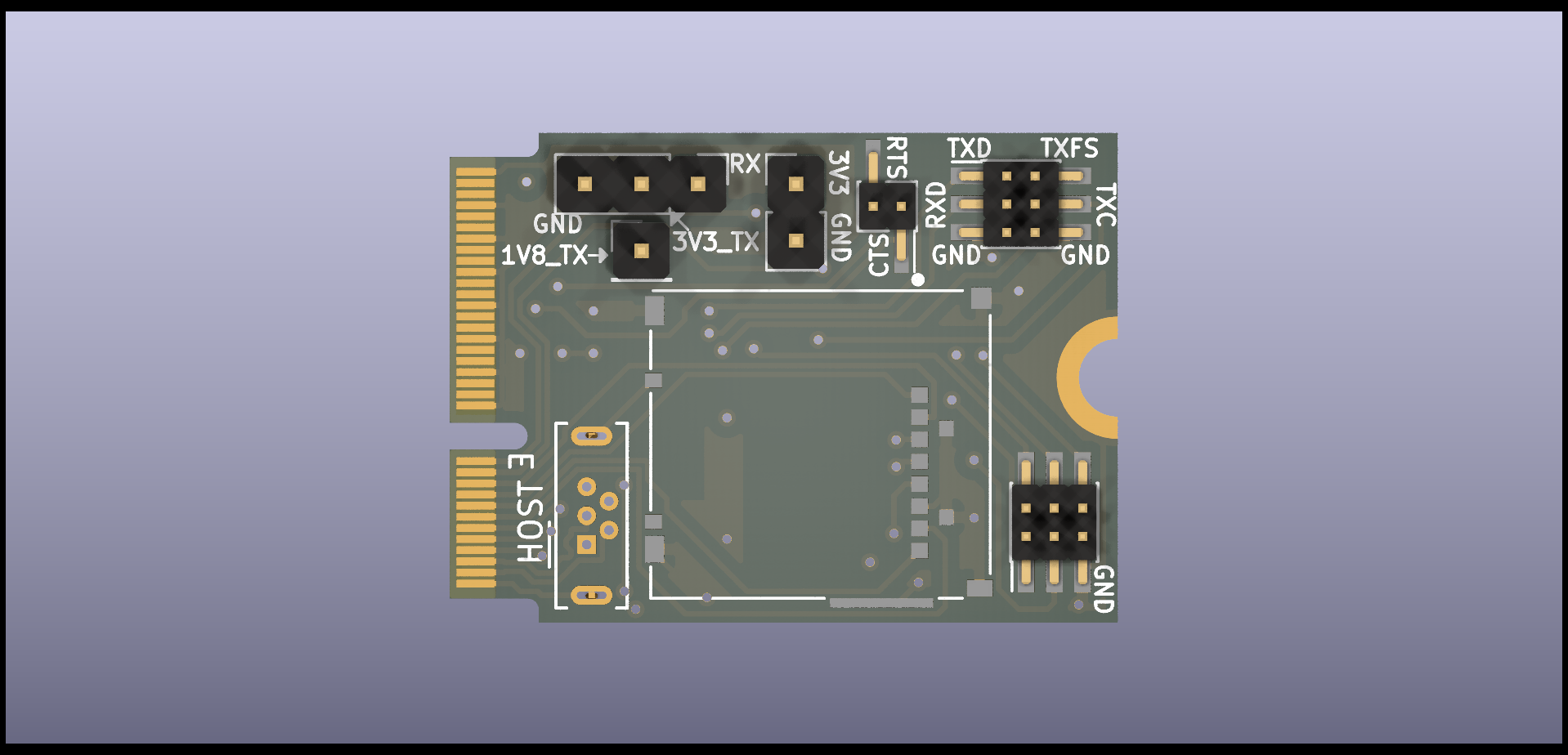
The Librem 5 m.2 key E breakout board uses UART4 and there are through hole pins labeled GND, RX, and 3V3_TX that are used for debugging. The 1V8_TX pin is the signal coming from the i.MX 8M which is not level shifted to 3.3V.
You will need to use a version of U-Boot that makes use of UART4 instead of the default UART1 interface. Of course, this board will occupy the M.2 slot that the WiFi module uses, so this means no WiFi while this breakout board is in use.
